his article originally appeared in the May’23 magazine issue of Electronic Specifier Design – see ES’s Magazine Archives for more featured publications.
The cards boast the highest sampling rate and bandwidth in company history, creating a powerful package for engineers and scientists working with today’s most challenging GHz-range electronic signals.
The one-channel M5i.3350-x16 and the two-channel M5i.3357-x16 feature front end circuitry with over 3GHz bandwidth and up to 16GB (8 GSamples) on-board memory. They also reach the fastest digitiser data transfer speeds, over PCIe, on the market. Using 16 lane, Gen 3, PCIe technology, data can be streamed over the bus at a staggering 12.8GB/s. The data can be sent to PC memory for storage, or directly to CPUs and CUDA-based GPUs for customised signal processing and analysis.
With 12-bit resolution, the digitisers offer better dynamic range than most conventional test instruments. For example, they deliver 16x more resolution than many digital oscilloscopes, which typically use 8-bit analog to digital converters. The front-end circuitry offers programmable full-scale ranges from ±200mV to ±2.5V together with variable offset. Acquisitions can be made in single-shot or multiple-waveform recording modes. To help capture the most elusive signals, a host of trigger modes are available for use on the channels or external trigger inputs. The modes include conventional edge triggering, along with more sophisticated methods such as Window, Re-Arm, Or/And (logical), Software, and Delay.
The cards can turn almost any PC it into a powerful measurement tool just by installing them in a suitable PCIe slot. This opens the door for anyone wishing to use the latest CPU and GPU hardware for signal processing and analysis.
The new cards come with a five-year product warranty and all the tools necessary to use them in a PC running either a Windows or Linux operating system. A software development kit (SDK) is provided, so that the cards can be programmed with almost any popular language including C, C++, C#, Delphi, VB.NET, J#, Python, Julia, Java, LabVIEW, and MATLAB. Alternatively, the company offers SBench 6 Professional.
This powerful measurement software provides full card control, along with a host of data display, analysis, storage, and documentation capabilities.
A low-cost option, M5i.33xx-spavg, is available for summation averaging using on-board FPGA technology. Averaging reduces unwanted signal noise while enhancing dynamic range and SNR. The cards can average signals at an astonishing rate of up to 15 million events per second, making them one of the fastest signal averaging solutions on the market.
Enhancing radar resolution range
The M5i.33xx-x16 series digitisers, with over 3GHz bandwidth and 10GS/s maximum sampling rate, are well matched to a broad range of RF and high-speed digital applications. One such RF application is radar analysis. Figure 1 shows an example of acquiring a 1GHz, phase modulated radar pulse.
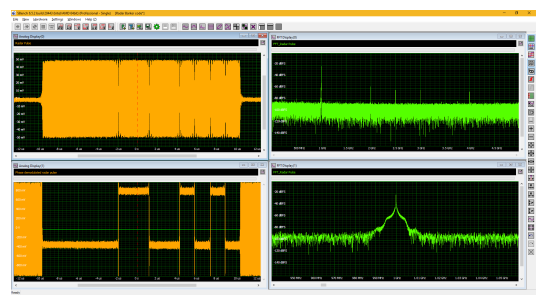
The radar pulse is acquired with the maximum sampling rate of 10 Giga Samples per second (GS/s) shown on the Spectrum Instrumentations SBench 6 measurement software. The phase modulation is a bi-phase Barker code intended to improve the range resolution of the radar. They are a sequence of numbers of different lengths of +1 and -1. The acquired data was transferred to MATLAB where the phase demodulation was performed, and the demodulated signal imported back into SBench6.
A software development kit (SDK), that includes drivers that allow common third-party analysis software like LabView and MATLAB to control and communicate with the digitiser, is included. The digitiser also can transfer the data at up to 12.8GB/s via the PCI Express x16 interface to the PC system or do a direct transfer to a CUDA GPU for custom processing. These interfaces provide the ability for further advanced analysis.
The Fast Fourier Transform (FFT) of the acquired signal shows the frequency spectrum of the signal. As expected, it has a peak at the carrier frequency of 1GHz. A horizontal zoom expansion of the FFT at the carrier frequency shows the spectral broadening due to the phase modulation.
In this application the long record length of up to 8 GSamples is also very useful to study tracking histories of up to 800ms at the 10GSps maximum sampling rate. The measured pulse has a duration of 20s and, at a 10kHz pulse repetition frequency of 10kHz, about 8,000 such pulses can be acquired in each record.
Communications measurements are another application area where the M5i,33xx-x16 series digitisers can be employed. Most communications systems use a variety of quadrature modulation schemes to efficiently encode data. Figure 2 illustrates an analysis of an 8PSK modulated 1GHz carrier.
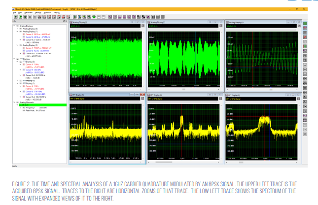
A 20s length of the acquired 8PSK signal is shown in the upper left trace in the SBench 6 display. Below that trace is the frequency spectrum of the signal. The spectrum shows a peak at the carrier frequency of 1GHz with its modulation envelope. The third harmonic of the carrier at 3GHz is visible and attenuated by about 36dB from the carrier peak. The bottom centre trace shows an expanded view of the spectrum. Cursors measure the offset of the closest modulation sideband to the carrier frequency.
Expanded spectrum view
The cursor readout, shown in the info panel to the left, reads the sideband offset as 160MHz from the carrier frequency. The modulation envelope for an unfiltered pulsed waveform would have a sin(x)/x shape. The 8SPK signal has been low pass filtered with a raised root cosine filter with a bandwidth of 20MHz. This is shown in the expanded spectrum view in the bottom right trace. The cursors measure the nominal bandwidth of the filter. The frequencies above the 20MHz cutoff are eliminated from the modulated signal spectrum so the sidebands appear only within 20MHz of the carrier and sampling nulls.
The top centre trace is an expanded view of the acquired time signal. The ripples are due to the data modulation. The spacing between two adjacent narrow peaks provides insight to the data rate of 40 Mbaud. The 160MHz spacing between the modulation sidebands indicates an additional sampling process at four times the data rate, or 160MHz. Looking at the highly expanded view of the 8PSK signal in the top right trace you can see the granularity in signal between phase breaks. The cursors are set to measure the time period between phase breaks, and it turns out to be 6.2ns, or a frequency of 160MHz. So, the 40 Mbaud modulation is band limited to 20MHz and sampled again at 160MHz before being broadcast.
The acquired RF carrier was demodulated externally to SBench 6, using proprietary vector signal analysis software, and then the resultant in-phase and quadrature components are re-imported back into SBench 6 for additional analysis and display. Figure 3 provides an example of the results. The I component is shown in the upper left trace, the Q component is shown below the I component.
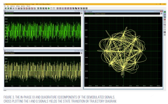
The 8PSK signal encodes three bits into every symbol producing eight possible data values per symbol. The I and Q values translate into phase and magnitude information. The phase and amplitude value of each of these states can be shown in a plot of the I signal versus the Q signal, what is known as a constellation diagram. The state transition or trajectory diagram (in the right-hand trace) shows the transition paths between data states. Each trajectory starts and ends at one of the eight data states. The data states occur at eight phases of 0, 45, 90, 135, 180, 225, 270, and 315 degrees. The state transition diagram provides a quick way of evaluating the 8PSK signal generation. Asymmetry and skew of the underlying constellation indicate errors in signal generation.