The performance of electromechanical systems such as those used in electric vehicles (EVs), smart buildings and medical devices, for example, is not just determined by the performance of its individual components. Today’s increased incorporation of power electronics and switching devices in system design, means it is not sufficient to merely measure the power consumption and performance of these components to understand the overall performance and behaviour of a system; there is an increasing need to accurately measure both the power behaviour of the applied power electronics and other interrelated electrical and physical parameters.
There is a range of instruments that can be considered to perform some or all the measurements and calculations to determine the behaviour characteristics. Choosing the most appropriate instrument is not just about saving money, it is about being able to meet the increasingly tight and demanding development timeframes to get products to market.
In order to establish the correct types of measuring equipment that are required for testing power electronics systems, it is useful to look at the various stages in the development of the system, which can be summarised: architecture and design, verification and prototyping and efficiency validation.
 Figure 1: A typical automotive electric drive system
A typical automotive electric drive system, as shown in Figure 1 can help a user explore the testing requirements for each of these stages.
Architecture and design
During this exploratory stage, bear in mind that the test process is carried out on a system consisting of individual parts and that key factors in the selection of a test instrument include the need to examine fast inverter switching, high-frequency dynamic behaviour, overshoot on pulses, and the need to trigger on individual waveforms.
Measurements of this type require an oscilloscope; ideally a mixed-signal instrument with multiple channels. Eight is an ideal number to view input and output signals in three-phase systems. For architecture and design, the multi-channel, mixed-signal oscilloscope provides insight into the high-frequency behaviour of individual components including the analysis of phenomena such as overshoot and ringing in pulse width modulated (PWM) waveforms with tests over a relatively short measurement period.
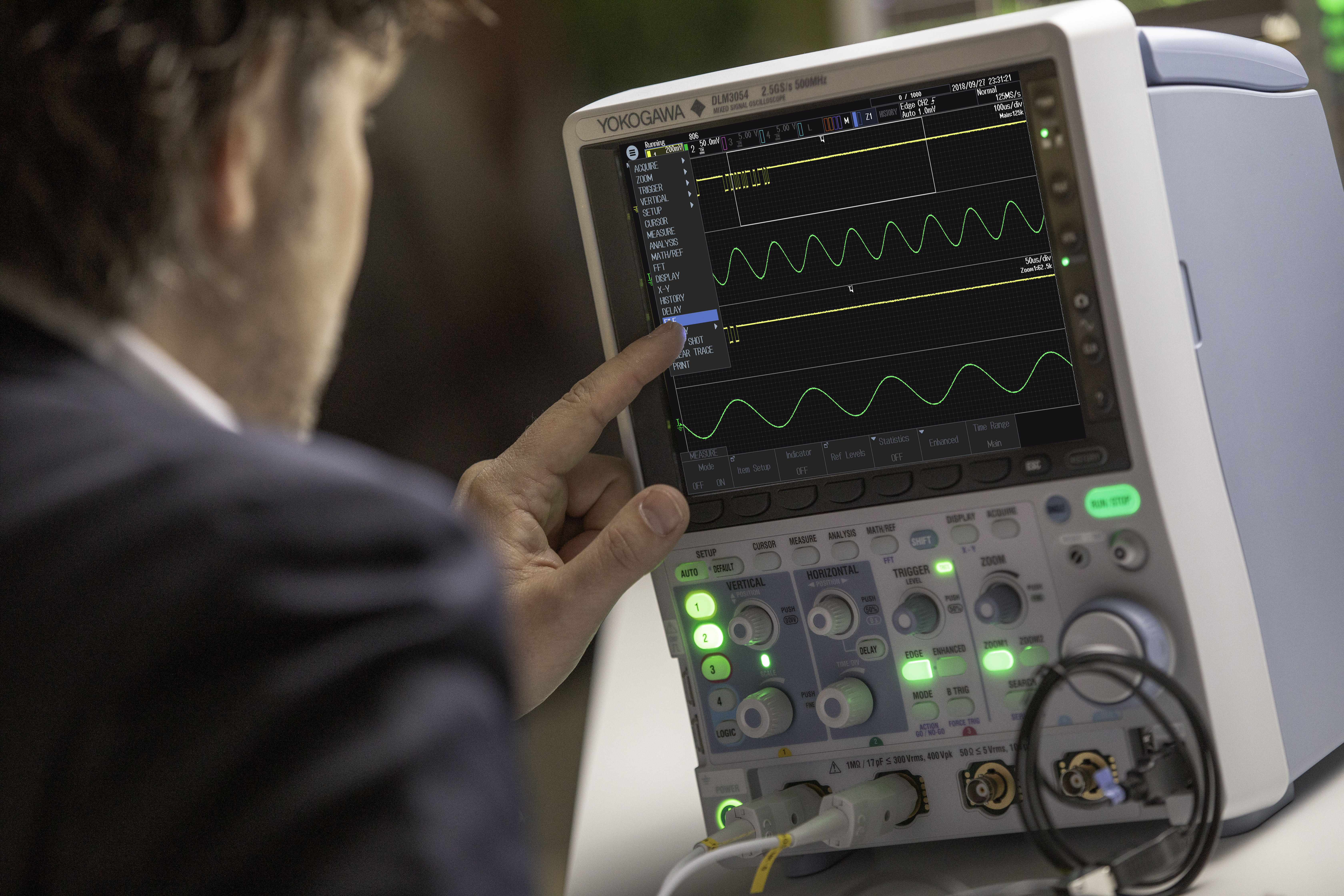 Figure 2: The DLM3000 MSO
In this application, there is a need to have the capability for serial bus testing on a variety of in-vehicle buses as well as a dedicated power supply analysis capability for testing inverters and other drivetrain components of electric and hybrid vehicles. This reliably captures and analyses waveforms in detail.
Holistic measurement in the key areas of power electronics and hybrid and EV drivetrains, the DLM3000 (Figure 2) is a mixed signal oscilloscope that offers dedicated serial bus analysis options for embedded systems and in-vehicle buses such as I2C, SPI, CAN, CAN FD, LIN and SENT. Potentially complicated trigger and decode settings, such as bit rate and threshold level, are automatically detected using the auto setup function.
Simultaneous analysis of four different buses can be carried out, with waveforms and analysis results from buses with different speeds being displayed using dual zoom windows. In this way, latencies and system performance across the different buses can be directly related.
Verification and prototyping
For verification and prototyping, a ScopeCorder provides a thorough insight into the overall dynamic behaviour of an electromechanical system by linking the cause and effect of interdependent parameters. This includes the ability to calculate and trend power-related signals and trigger at the appropriate point. Flexible inputs offer a choice of voltage or current measurements, sensors for physical parameters and CAN/LIN bus signals, with measurements over periods from milliseconds up to multiple days.
ScopeCorders are powerful data acquisition recordersthat can capture and analyse a variety of electrical, physical sensor, and serial bus signals as both transient events and trends for up to 200 days.
Using flexible modular inputs, they combine measurements of electrical signals, physical sensors and CAN/LIN/SENT serial buses and can trigger on electrical power-related and other calculations in real time. As such a ScopeCorder is often perceived as one of the most powerful portable data acquisition instruments available on the market and combines the signal fidelity of a very high resolution oscilloscope with the long term data acquisition capabilities of a recorder. Measurement data can be thoroughly analysed in fine detail or viewed as trends over long periods of time. Its operation in harsh environments with isolation technology produces sample rates up to 100Msample/s, two to 128 analogue or 128 logic channels and isolated inputs up to 1000V.
Efficiency validation
For efficiency validation of an electric drive system, the power analyser is the dedicated tool for measuring and analysing power, including harmonics and distortion, with calibrated accuracy, precision and stability.
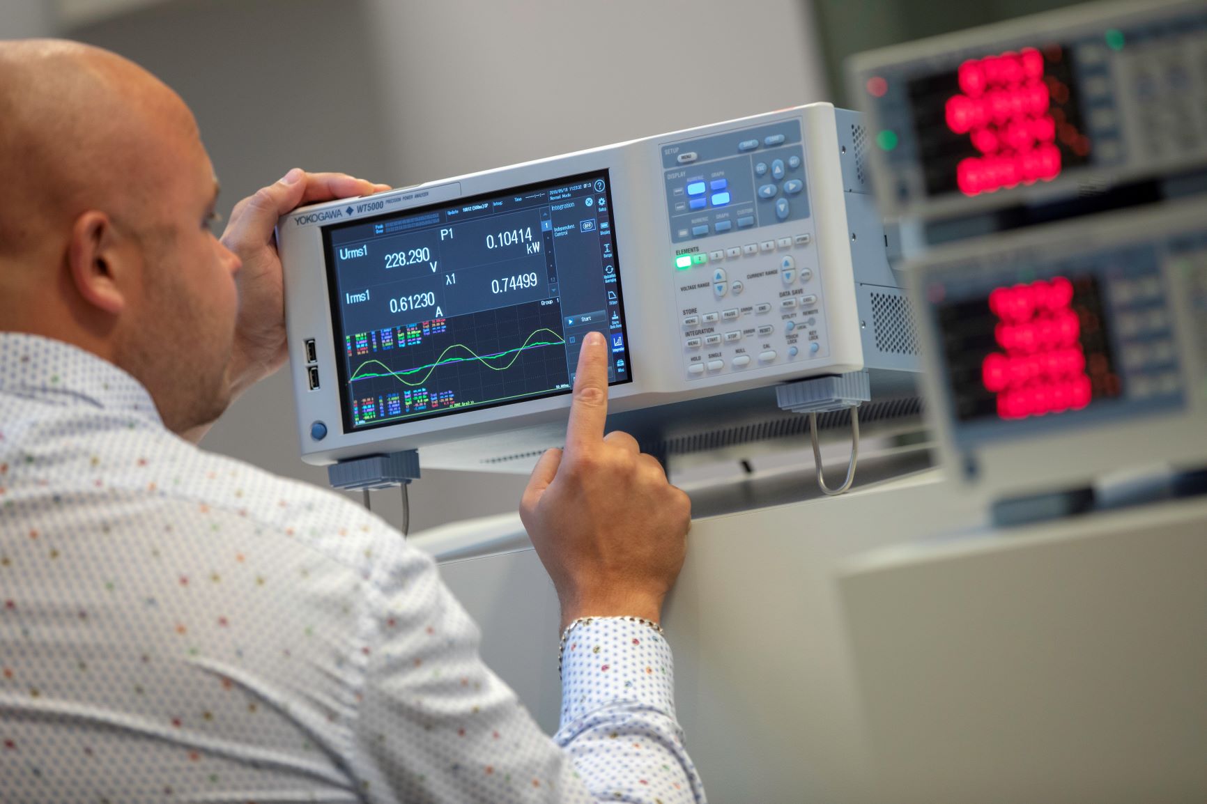 Figure 3: The WT5000 power analyser
For tests of this type, a power analyser offers precision, high accuracy, high stability, and the ability to carry out calibrated measurements. A power analyser needs to be able to simultaneously perform power measurements on up to seven sets of inputs, which makes it possible to perform efficiency tests between the input and output of products such as inverters. It can also accurately measure highly distorted voltage or current waveforms with high harmonic content. Harmonic analysis can be carried out up to the 500th order from a 50 or 60Hz fundamental frequency. This facility is especially important for measurements on new power conversion and power electronics devices.
A dual harmonic measurement function makes it possible to simultaneously measure the harmonic content and perform harmonic analysis on two different sources, such as the input and output of an inverter or variable-speed motor drive. The normal power parameters and harmonic data are measured simultaneously, providing faster and more accurate power analysis.
In order to develop axle drive inverters and analyse their efficiency, there is typically a requirement for seven power elements in the power analyser to enable, for example, automotive engineers to carry out all the measurements on the battery (DC), multiple inverter phases and the motor in one calibrated instrument.
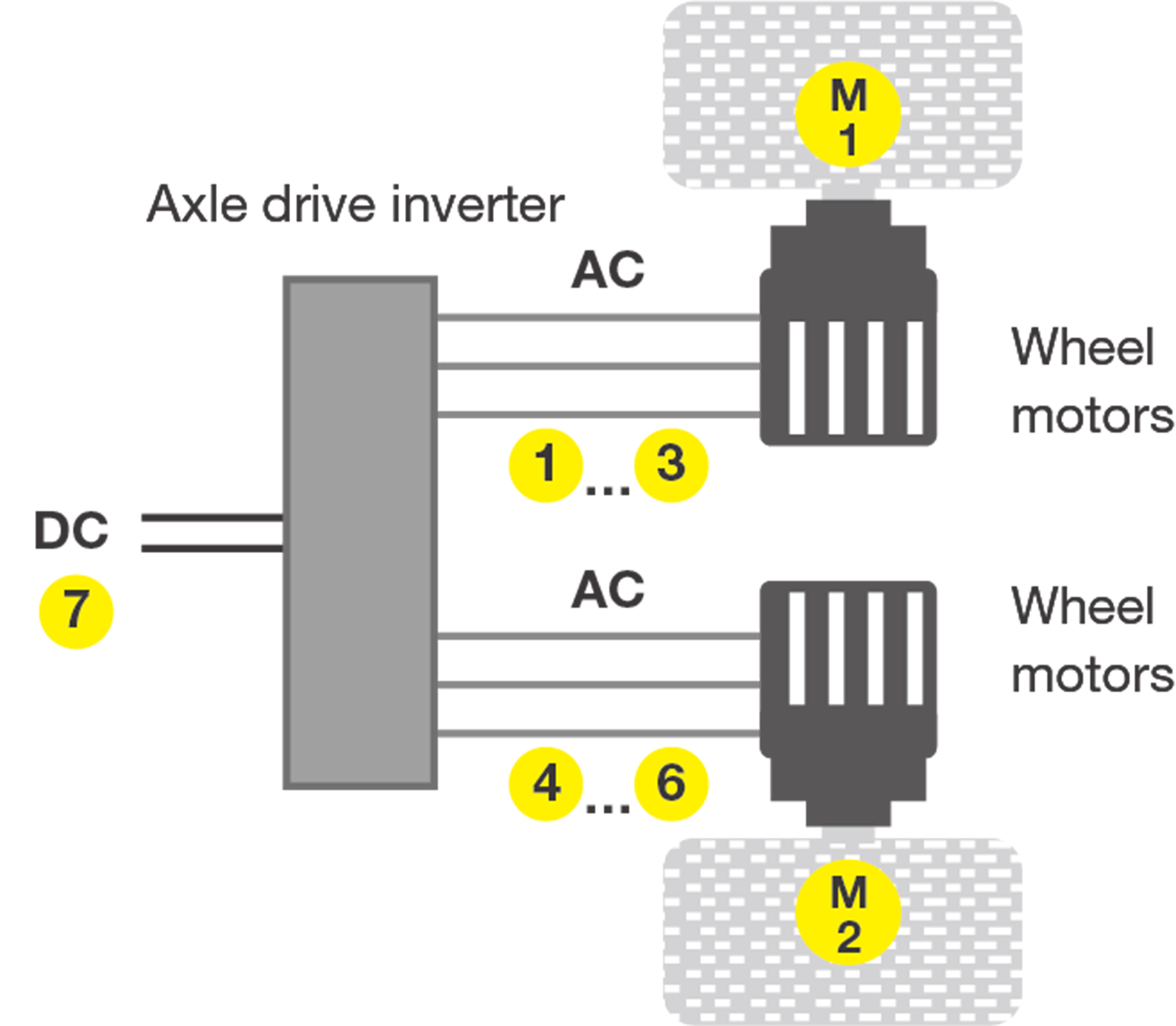 Figure 4: The e-drive inverter
This concept is illustrated by the e-drive inverter in Figure 4 which has two sets of three-phase outputs which each drive two individual wheel motors. These signals use six input elements on a power analyser, while a seventh input is required for the DC battery signal powering the inverter.
An example is the Yokogawa WT5000, which can evaluate the mechanical performance of up to four motors simultaneously. The measurement and evaluation of such factors as the motors’ torque, rotation speed and direction, and slip enable the electro-mechanical efficiency of the motors to be analysed as well.
Conclusion
Although this article uses examples from EVs to illustrate the applications for different classes of power measuring instruments, there are many other sectors of technology and industry where the same measuring principles are relevant. Examples include power generation and distribution, alternative energy, industrial automation and robotics – anywhere, in fact, where there is a need to save energy and maximise power efficiency.
PCIM Europe Visit Yokogawa Test & Measurement – Hall 9-200


