This article originally appeared in the March’24 magazine issue of Electronic Specifier Design – see ES’s Magazine Archives for more featured publications.
Meeting these requirements can be challenging using standalone test equipment. Instead, designers can opt for a modular approach using a standardised form factor like PCI eXtensions for Instrumentation (PXI).
Why use PXI?
As test beds become more complex, the use of standalone equipment results in multiple screens, front panels, and line cords, as well as slow instrument computer interfaces. This leads to confusion and unnecessary errors that extend test time and reduce productivity.
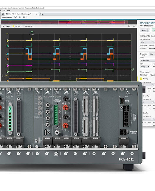
PXI instruments offer the needed functionality in a standard and compact form factor. In this scenario, multiple instruments like analog and digital input/ output (I/O) channels fit side-by-side in a common chassis. PXI also simplifies the addition and integration of more complex instruments like oscilloscopes, multimeters, and signal generators. The instruments communicate internally with a common bus structure, assuring synchronous operation, while a PC running unifying software allows all the instruments to be controlled from a common screen.
A common testing scenario
.png) Figure 1. A VSD uses multiple analog and digital sensors that need to be tested and their functionality verified. (Image source: Art Pini)
Figure 1. A VSD uses multiple analog and digital sensors that need to be tested and their functionality verified. (Image source: Art Pini)
An example demonstrates the type of measurements that the multifunction I/O module is designed to handle. It comprises a variable speed drive (VSD) in an intelligent motion control system that requires multiple types of sensors (Figure 1).
Testing the sensor components of a VSD ensures the correct operation of motor temperature, rotational speed, shaft position, torque, and vibration-level sensors. Most of the sensor outputs are analog signals with a low signal bandwidth of less than 1 megahertz (MHz).
Multifunction I/O test modules are well-suited to testing these types of sensors, offering analog voltage ranges, bandwidths, and sample rates matched to the analog sensor outputs. They also include digital I/O channels with sample rates greater than the data rates being tested.
The multifunction I/O test bundle
.png) Figure 2. A PXI multifunction I/O bundle provides a standalone automated test and measurement system, including a multifunction PXI I/O module and four open slots for additional instruments. (Image source: NI)
Figure 2. A PXI multifunction I/O bundle provides a standalone automated test and measurement system, including a multifunction PXI I/O module and four open slots for additional instruments. (Image source: NI)
NI’s PXI bundles consist of a five-slot PXI chassis and either of two NI multifunction I/O modules. The PXI multifunction modules offer a mix of analog I/O, digital I/O, counter/timer, and triggering functionality (Figure 2).
The chassis provides power and an internal bus structure to link all the modules via its backplane. The PXIe bus allows multi-instrument triggering and synchronisation. A Thunderbolt 3 interface provides a fast interface via a USB 3.0 connector to a computer. Two USB 3.0 connectors allow daisy chaining of multiple PXIe chassis. The four open slots can accommodate other instruments.
For example, NI’s 867123-01 multifunction I/O bundle consists of a PXIe-1083 five-slot chassis, a PXIe-6345 multifunction I/O module, and associated cables. Alternatively, the 867124-01 bundle uses the same chassis and cabling but uses a PXIe-6363 module with input mass termination connectors on the front panel (Figure 3).
The two product bundles differ in the number of analog input channels, the number of analog output channels, the number of digital I/O channels, and the maximum sampling rate (in kilo samples per second (kS/s) and mega samples per second (MS/s)) (Table 1).
.png)
Figure 3. A detailed view of the PXIe-6363 multifunction I/O module includes a view of the input mass termination connectors on the front panel. (Image source: NI)
Analog channels
Both bundles’ analog input (AI) channel internal configurations are identical. A single analog-to-digital converter (ADC) is shared over multiple input channels using an analog multiplexer (Mux) to sequence each input (Figure 4).
Input signals are connected via the front panel I/O connector. In addition, the AI sense connection and the AI ground are also available to establish accurate reference levels for measurements. There are three input configurations: differential, referenced single-ended (RSE), or non-referenced single-ended (NRSE).
The RSE input configuration ties the inverting input (AI-) to ground at a single point, either at the AI ground for a floating source or at the source ground for a ground-based source.
The NRSE configuration for a floating source connects the AI- input to the negative terminal of the source and to the AI sense line with a resistive return to AI ground. For a ground-referenced source, the AI- terminal connects directly to the source ground and to the AI sense line.
.png) Figure 4. The configuration of the analog channel inputs includes a Mux to route the individually configured inputs into a single ADC. (Image source: NI)
Figure 4. The configuration of the analog channel inputs includes a Mux to route the individually configured inputs into a single ADC. (Image source: NI)
The configured input is routed to the NI programmable gain instrumentation amplifier (NI-PGIA), which amplifies or attenuates the incoming signal to match the input voltage range of the ADC. There are seven programmable input voltage ranges for the analog signals between ±100 millivolts (mV) and ±10 volts.
The ADC for both digitisers has a 16-bit amplitude resolution. The analog signal is quantised into 65,536 possible levels. This provides 320 microvolts (v) resolution in the ±10 volt range, and 3.2v in the ±100 mV range.
The digitised outputs of the ADC are stored in the AI first in, first out (AI FIFO) memory. The multifunction modules also have an analog output (AO) capability. There are either two or four analog outputs, depending on the model, with a common output clock (Figure 5).
The AO FIFO memory buffer holds the waveform sample values downloaded from the host computer. Having the samples stored in the FIFO means that analog waveforms can be output without the computer connection. The AO Sample Clock clocks the data from the FIFO into the digital-to-analog converters (DACs). The AO Reference Select is used to change the analog output range and can be set to 10 or five volts, or an external reference can be applied via the analog PFI (APFI).
Digital channels
Digital channels include both input and output capabilities to acquire or generate digital signals on a common line (Figure 6).
.png) Table 1. Shown is a comparison of the PXIe-867123 and PXIe-867124 multifunction I/O bundles. (Table source: Art Pini)
Table 1. Shown is a comparison of the PXIe-867123 and PXIe-867124 multifunction I/O bundles. (Table source: Art Pini)
The P0.x lines work with static or high-speed digital lines as inputs or outputs. The PXIe-63xx series modules also have sixteen Programmable Function Interface (PFI) lines that can be user-configured as a PFI interface or a digital I/O channel.
There is a digital filter on each digital line that is used to debounce the digital input signals. There are three filter settings based on the filter clock frequency used: short, medium, or high. The short setting guarantees that a pulse width of greater than 160 nanoseconds (ns) will pass, the medium setting passes pulse widths of 10.24 microseconds (s) or greater, and the high setting passes pulse widths of 5.12 milliseconds (ms) or greater. Pulses with widths narrower than half the passed pulse width are guaranteed to be suppressed.
.png)
Figure 5. In a typical analog output stage, the AO FIFO memory buffer holds the waveform sample values downloaded from the host. (Image source: NI)
.png)
Counter/timers
Both PXIe modules include four general-purpose 32-bit counter/timer stages and a frequency generator stage. There are eight signal input paths to each counter/ timer stage, and the input of the counter timer can be any of fourteen available signals. The selected signal must be applied to the clock; there is no provision to count down the counter/timer input. The counter/timers can be used to count edges, measure frequency or period, or take pulse measurements like width, duty cycle, or the time between two edges.
Software support
Several software packages support multifunction I/O modules. NI’s LabVIEW provides a graphical programming environment that simplifies data acquisition, processing, and analysis. For users who wish to generate their own code, NI supplies drivers supporting the programming language of choice, including Python, C, C++, C#, .NET, and MATLAB.
NI also offers a no-code software package called FlexLogger. FlexLogger lets users view, save, and analyse test data with built-in processing tools and customisable dashboards (Figure 7).
.png)


