


Edward Ng, Thermal Solution Product Manager at Panasonic Industry Europe further explores.
All this – as we have said – is well known. Good design will see sensitive or heat-producing components or system elements mounted on, or close by, heatsinks and fans or directly attached to them. Even if the path is optimal when the device is new, it can degrade such that eventually the process of removing heat becomes ineffective. This article looks at a variety of ways to achieve good interfacing between heat sources and heatsinks while focusing on solutions for power modules, including a new material that solves many of the challenges faced by design and production engineers.
When cooling heat-generating components using heatsinks, gaps can occur between the two adjoining surfaces, resulting in air pockets which increase the thermal resistance such that efficient cooling cannot be achieved. Therefore, these gaps must be filled using a thermal interface material (TIM) with a low thermal resistance.
Types of thermal interface material (TIM)
Around a long time, thermal grease is the most common and cheapest form of TIM. They are applied between heating elements and heat sinks. However, it is difficult to apply them evenly and repeatedly, and there is also an issue of long-term reliability since they can dry out and lose efficacy.
Phase change materials (PCMs) are somewhat more costly, but often deliver better performance than standard silicon-based thermal grease. They feature reduced contact thermal resistance due to improved adhesion caused by the softening at high temperatures. Although they are easy to handle, the materials are costly and have the issue of long-term reliability.
Thermal conductive sheets are made from a TIM such as silicon, elastomer, or graphite. Sheets are sandwiched between the heating elements and heatsinks; they are easy to handle but, due to their hardness, they require pressure to achieve adequate contact.
To save space, more and more power module are positioned vertically. With the power module in a vertical position, thermal greases, or even PCMs, are likely to discharge due to the gravitation accompanying temperature changes, leading to a medium-to-long-term degradation in performance. This effect occurs especially when the greases dry out, therefore many customers choose the thermal conductive sheet solution.
Key requirements for thermal interface materials
There are three main requirements for TIMs. First, they must have a low thermal resistance. This means they should achieve adequate contact in order to also allow for any warping or rough surfaces. Second, TIMs must have stable characteristics over the life of the equipment, and require no maintenance required. Lastly, they must be easy to attach and remove from the heatsink and power module without any significant investment in production in order to be simple to change in the field as well.
Graphite Sheet TIM
Pyrolytic, highly oriented graphite sheets are made of graphite with a structure that is similar to a single crystal. These sheets are produced from polymeric film using a heat de-composition process. The hexagonal structure of the graphite is uniformly arranged in a horizontal 2D position as shown in Figure 1.
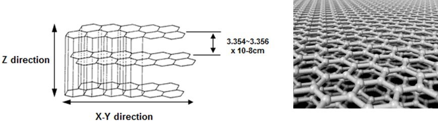
Figure 1: Hexagonal mono-layer of the graphite sheet
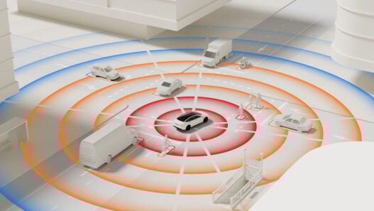
In applications like general power inverters, solar inverters or EV charging stations that use power modules, thermal grease is usually utilized to fill the voids caused by distortion and roughness of the contacting surface. Over time, the grease dries out or is ‘pumped out’ as a result of temperature changes and therefore needs replacing. This is a costly exercise, as either the entire system has to be exchanged or a technician must make a field call and remove the old grease, clean everything, apply new grease and re-assemble the system.
With pyrolytic graphite sheet technology, such as Panasonic’s GraphiteTIM, the sheet has been designed exclusively to act as a thermal conductor, replacing the conventional grease or PCM. Graphite TIM is highly compressible and thus fits well to the uneven surfaces, reducing thermal contact resistance which results in high heat dissipation, high reliability, and easy handling (Figure 2).
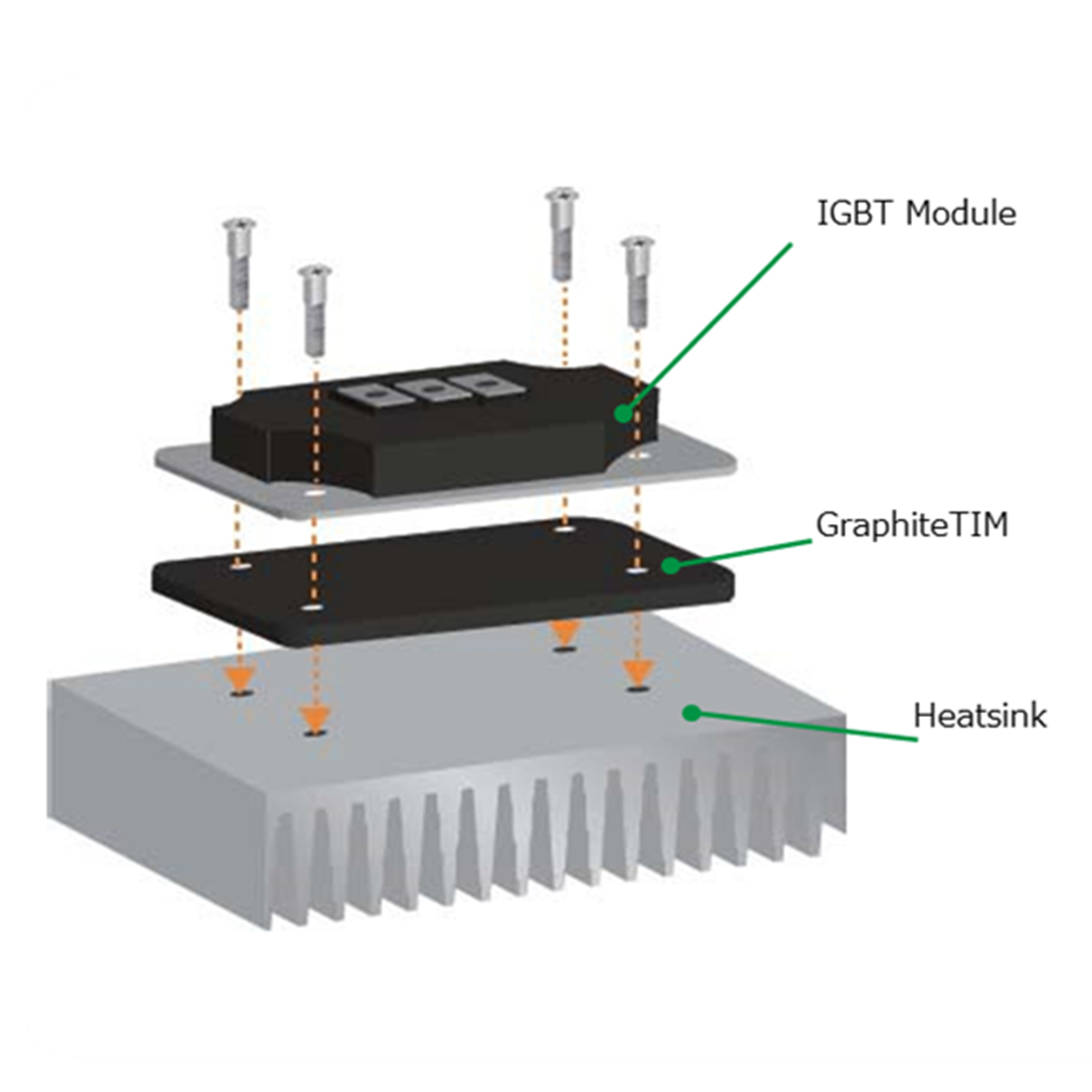
Figure 2: Standard assembly of a IGBT/SiC module with TIM and heatsink
GraphiteTIM characteristics
As opposed to other thermal interface materials, GraphiteTIM diffuses heat not only in Z direction but also distributes heat across the X-Y plane, thereby delivering a much better cooling effect (Figure 3).
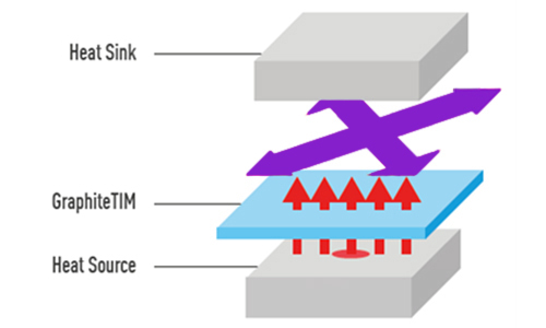
Figure 3: Heat distribution across the plane and dissipation at the heatsink
Typical characteristics of the Panasonic GraphiteTIM material are shown in Table 1.
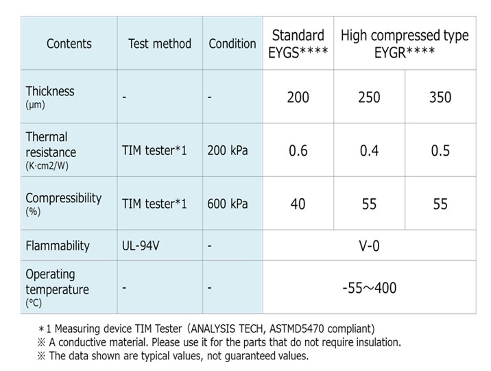
Table 1
Compressibility and thermal resistance
Panasonic’s GraphiteTIM is considerably softer than comparable graphite sheet materials. Because of its high compressibility it can fill voids more effectively. Generally, standard thermal graphite sheets have a compression rate of 20%, while graphite TIM offers compression rates up to 60%. To achieve this high compression, the contact pressure should be 300 kPa to 600 kPa (Figure 4a and 4b).
When adequate pressure is applied, the initial thermal resistance of GraphiteTIM drops well below the level of common thermal greases. (Figure 5).
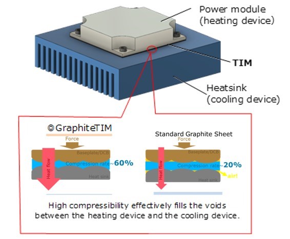
Figure 4a: Impact of compressibility on the contact

Figure 4b: Compressibility as a function of the contact pressure
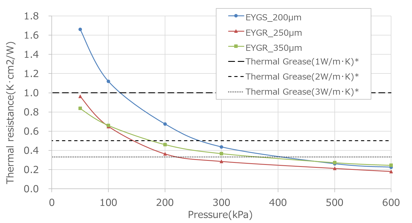
Figure 5: Thermal resistance from GTIM and thermal greases as a function of the contact pressure
Reliability
The more reliable the thermal interface material is, the longer the life-time and robustness of the application due to reduced thermal stress on it. Long-term tests demonstrate that the performance of GraphiteTIM remains constant after many thousand cycles, while the effectiveness of thermal pastes diminishes after just a few hundred cycles. (Figure 6).
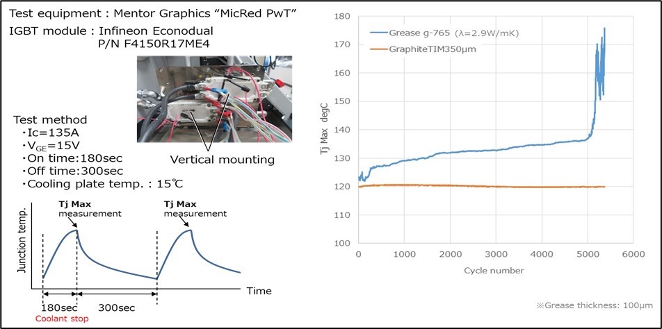
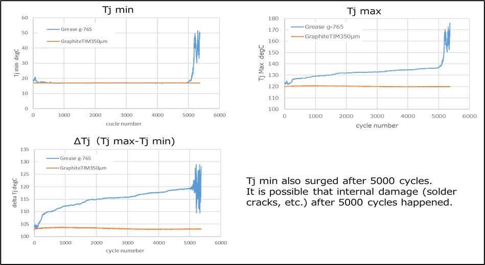
Figure 6: Long-term tests of GraphiteTIM and thermal grease
Ease of handling
Figure 7 compares the application of thermal greases and PCMs with GraphiteTIM. Whereas positioning the sheet can be accomplished in one step, using thermal paste involves multiple steps, including preliminary treatment, application, drying and cleaning.
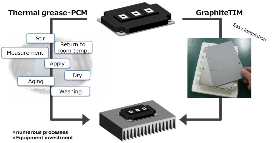
Figure 7: Application process for GTIM and thermal pastes
Choosing the right sheet thickness
Panasonic offers three different thicknesses of GraphiteTIM to bridge the gap between heat source and heat sink. The optimal sheet thickness mainly depends on three parameters:
- Size of the module
- Applied pressure (e.g., number and position of screws, torque)
- Type of baseplate
Table 2 shows Panasonic’s recommendations based on these parameters.
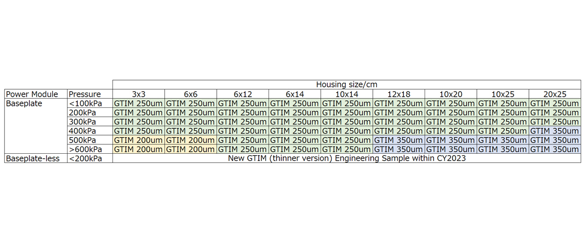
Table 2: Sheet thickness recommendation based on size of the module and contact pressure
Standard designs for IGBT module
Panasonic currently offers GraphiteTIM in 56 standard shapes that are compatible with several hundred power modules, including products from Semikron, Hitachi, Fuji, Infineon and Mitsubishi, as detailed in the GraphiteTIM selector tool at https://industrial.panasonic.com/ww/soft-pgs-cross. Custom shapes are also available. Semikron has also published an overview of GraphiteTIM sheets as applied to its modules and compares its performance with grease and PCM. Table 3 summarises the findings of this independent power module leader.