


If the insulation breaks and live metal parts are exposed, or shunts appear in the onboard electronics, life-threatening residual currents can occur in the EV user’s body.
To prevent electric shock accidents, manufacturers of EV supply equipment (EVSE) must incorporate residual current devices (RCDs) into their power electronics products that trip within a few milliseconds for both AC and DC residual currents of a few milliamperes (mA).
Rolf Horn, Applications Engineer, DigiKey further explores.
Residual currents in the EV charging circuit
Charging EVs at voltages up to 400 volts AC and 1,000 volts DC requires extensive protective measures for the EV user when handling charging equipment. Power electronic circuits such as rectifiers, switching converters, frequency inverters, along with inverter and phase-angle control systems, have a wide variety of load current characteristics. The resulting potentially dangerous residual currents are categorized as sinusoidal AC, pulsed DC, and straight DC. Table 1 shows typical load current signals of various circuit topologies and the resulting residual current waveforms.
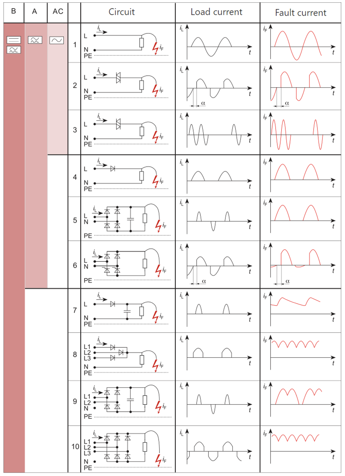
Table 1: Fault current forms and their detection according to the type of RCD that is most suitable (columns 1 to 3). (Image source: Wikipedia)
A good knowledge of residual current waveforms can help EV repair shops and electricians when tracking down residual currents.
Tripping characteristic of RCD types
In general, personal protection against electric shock on electrical installations is regulated by IEC 60479 and UL 943. System designers can now easily implement specific personal protection requirements in the charging circuit by selecting an RCD type of the appropriate standard. Table 2 lists residual current forms and trip tolerance of the different RCD or ground fault circuit interrupter (GFCI) types.
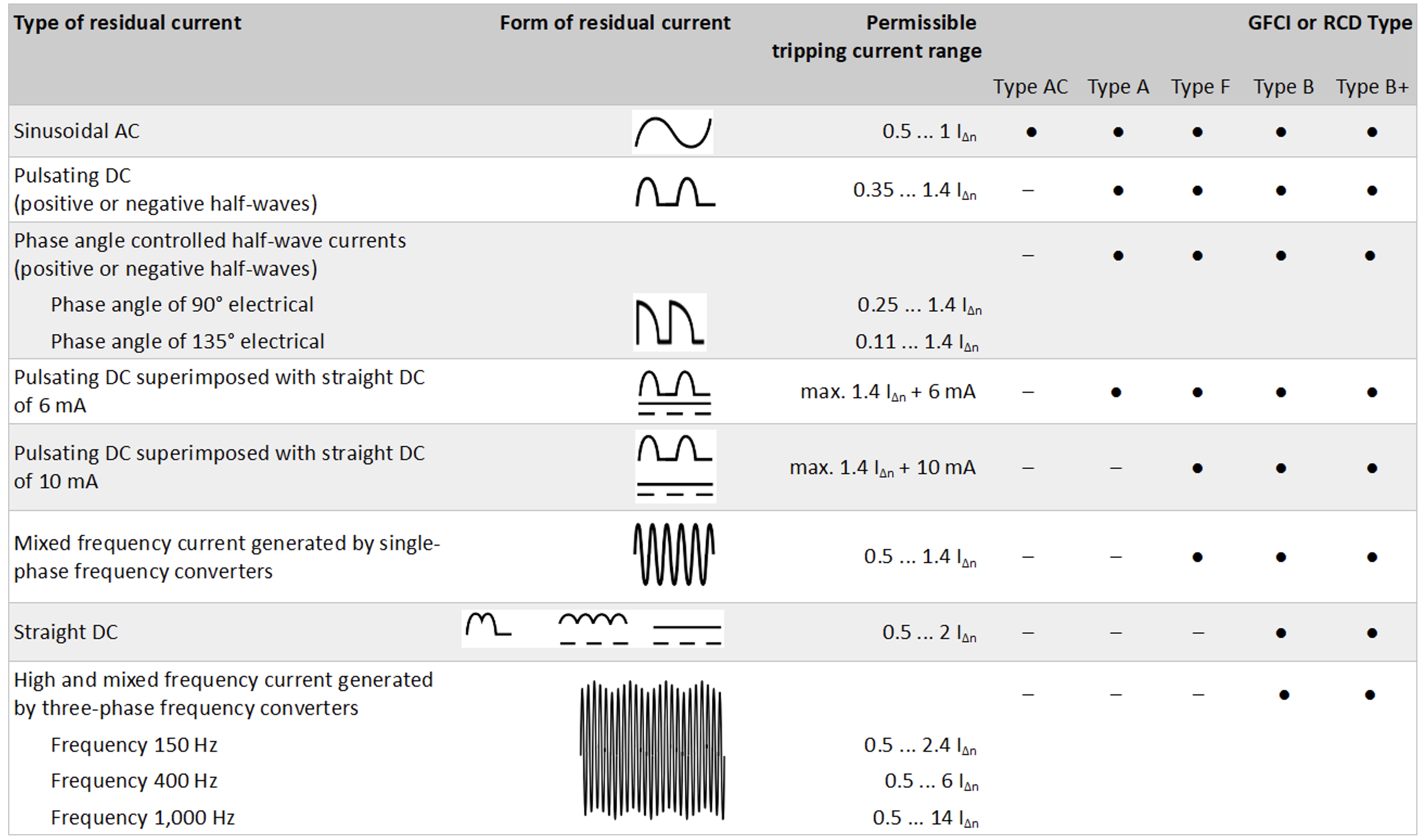
Table 2: Tripping characteristics of different GFCI or RCD types. (Table source: abb.com)
Installing RCDs in the EV charging circuit
Type-A or Type-F RCDs only detect AC residual current and DC pulsating current, which is insufficient for protecting an EV charging circuit. The IEC 62196 standard, therefore, defines two residual current protection options: the use of an all-current sensitive RCD of Type B (or Type B+), or an RCD of Type A in conjunction with a residual DC monitoring system according to IEC 62955 with IΔn DC ≥ 6 mA.
Since an AC-sensitive Type-A or Type-F RCD is usually present in building electrical systems, designers can cost-effectively add 6 mA residual DC monitoring to Mode 3 wall boxes or charging stations, as well as to the in-cable control boxes (ICCB) of Mode 2 charging cables (Figure 1, cases 2 and 3).
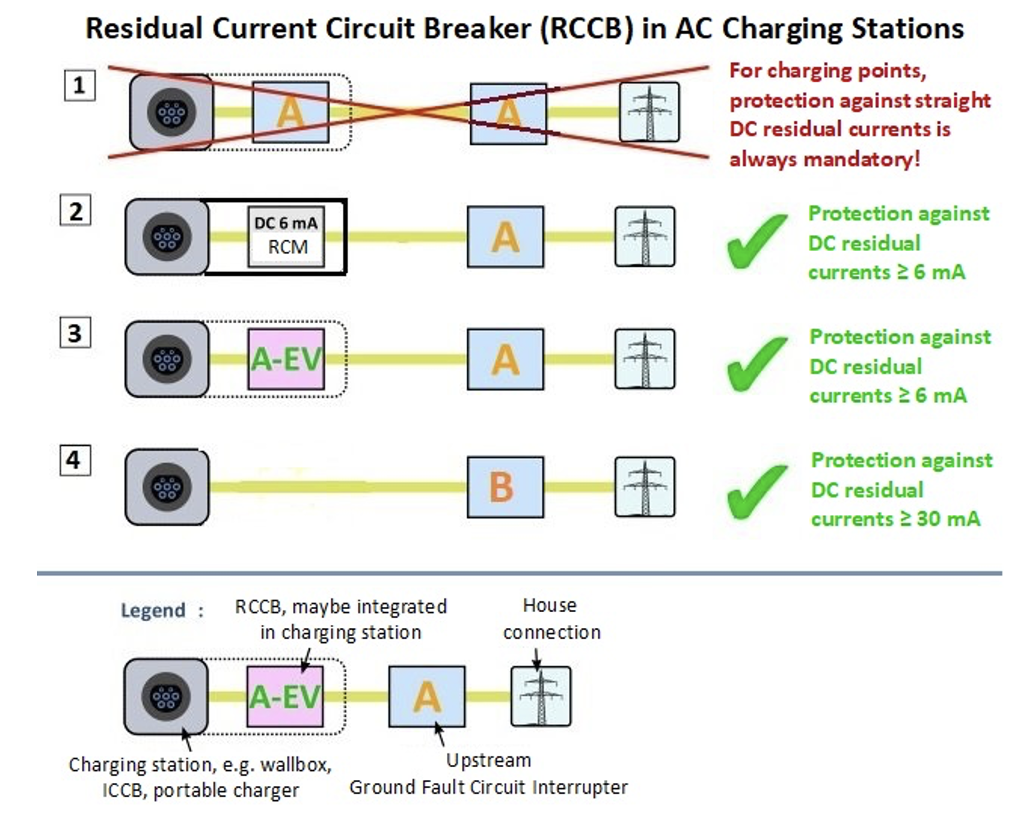
Figure 1: EVSE devices must add a DC residual current monitor downstream of the AC-sensitive Type-A RCD (case 2), or have one connected to AC mains directly via a Type-B RCD (case 4). (Image source: goingelectric.de)
Charging modes for EVs
The EV battery can be charged via different charging modes. In Europe, electrical energy can be fed into the vehicle via single-phase AC (230 volt/3.6 kilowatt (kW), three-phase AC (400 volts/22kW), or via high-voltage DC charging stations (up to 1,000 volts DC/500kW). Figure 2 illustrates the four charging modes defined in the IEC 61851 standard.
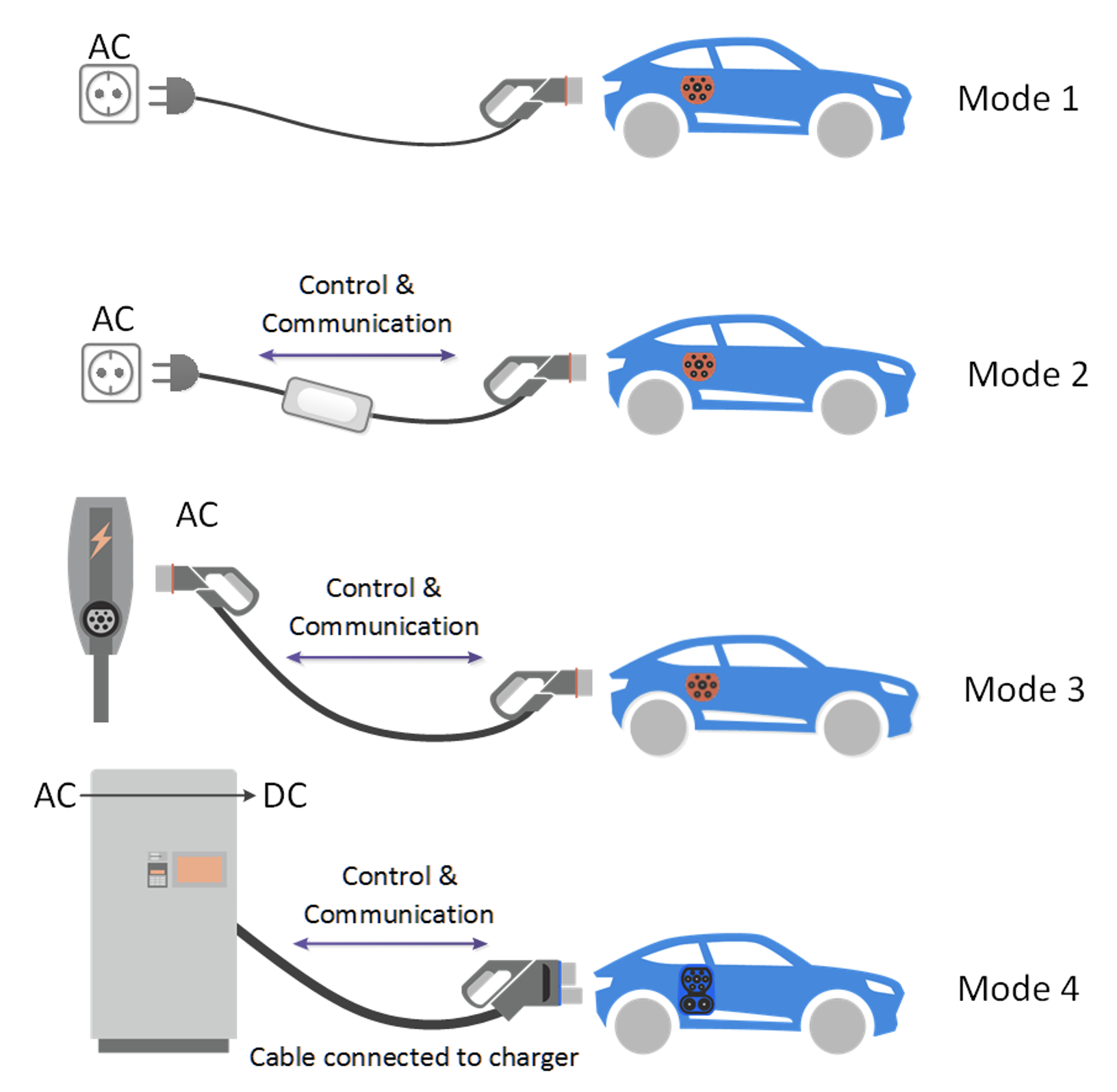
Figure 2: Illustration of the four charging modes defined in the IEC 61851 standard. (Image source: bestchargers.eu)
Mode 1 (single-phase AC charging up to 3.6 kW; default mode of charging)
In this case, the electric or hybrid vehicle is connected to a standard 230 volt household socket using a simple passive cable, and will be charged using low power at a maximum of 3.6kW via the onboard charger. This charging scenario does not provide sufficient protection against residual DC for the user.
Mode 2 (single/three-phase AC charging up to 22kW via an ICCB charging cable)
A Mode 2 charging cable equipped with a Type 2 vehicle plug contains an ICCB that performs safety and communication functions when charging EVs using domestic and three-phase sockets to prevent overloading them.
The following protection functions must be integrated with the ICCB:
- Determination of polarity and protective conductor (PC) monitoring
- Testing of the electrical connection between the PC and the metal body
- An AC and DC residual current circuit breaker
- Monitoring/shutdown of the charging process
- Monitoring of the temperature inside the ICCB and both plugs, and perform shutdown if necessary
- Control of the charging power
Mode 3 (single-phase/three-phase AC charging up to 22kW via wall box)
For EV charging, a passive Mode 3 cable is connected to a wall box in private households or a public AC charging station in parking lots. Both have integrated the same protection functions as the ICCB above.
Mode 4 (direct battery DC fast charging up to 500kW)
DC high-power charging stations for EVs deliver significantly higher charging currents compared to Mode 2 and Mode 3. Shock protection from residual AC and DC is implemented in this supercharger; the different charging cables are always firmly attached.
Measure AC and DC fault currents in the EVSE circuit
Residual current monitors (RCMs), from the RCM14 series from Littelfuse Inc., detect DC and/or AC residual currents in AC or DC systems and deliver an output signal to control an external disconnect (cutoff relay). In contrast, RCDs and residual current circuit breakers have an integrated cutoff relay.
AC residual currents are detected using an inductive current transformer (CT). For this purpose, the current forward conductor (IL) and current return conductor (IN) are fed through a soft magnetic toroidal core, causing both current vectors to normally compensate for each other and add up to zero. If a fault current (Ig) flows into the ground potential via the human body in the circuit behind the detector, the RCM or GFCI total current differs from zero, and the circuit breaker trips (Figure 3).
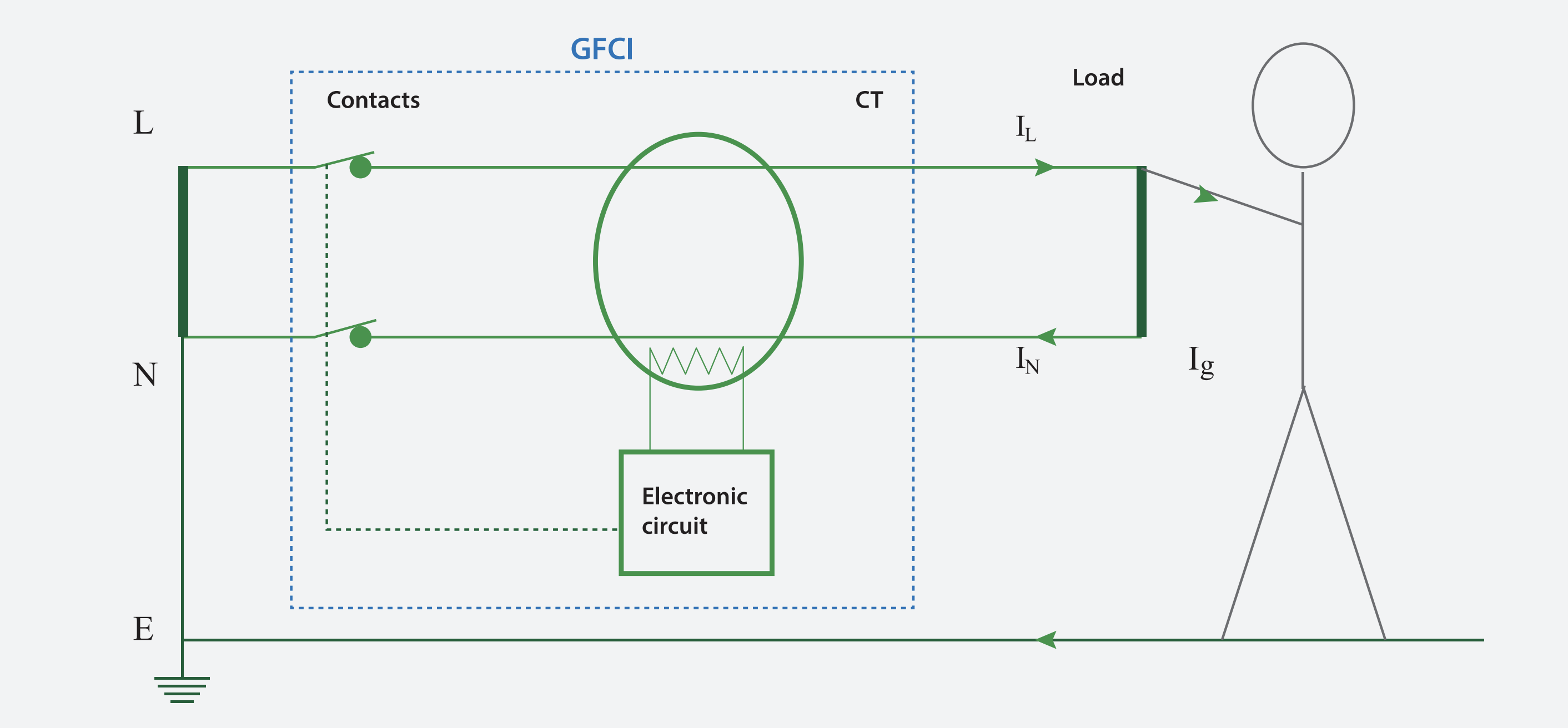
Figure 3: If a fault current (Ig) flows into the ground potential via the human body, the GFCI total current differs from zero, and the circuit breaker trips. (Image source: Littelfuse)
By integrating a fluxgate magnetometer probe into a slot of the toroidal core and compensating the magnetic flux to zero by means of a compensation coil, the CT can also detect differential DC. More accurate than Hall effect sensors or shunt resistors, this method detects tiny DC fault currents from 6 mA at heavy DC load currents up to 500 amperes (A).
RCMs featuring control output for disconnector
Littelfuse’s RCM14 series is ideal for use in ICCB charging cables for EVs (Mode 2) and EV charging stations (Mode 3). They are available in three residual current detection options in accordance with IEC 62752 (Mode 2), IEC 62955 (Mode 3), and UL 2231.
Each RCM has one operation LED and one fault LED. The four-pin JST connector simplifies the installation (Figure 4).
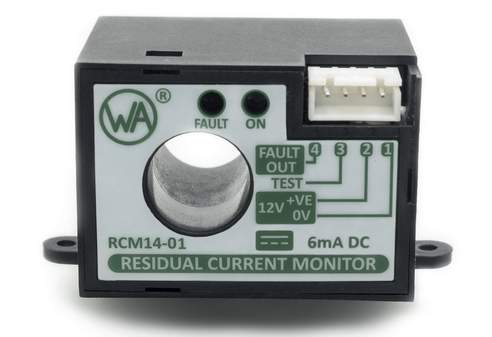
Figure 4: The RCM14 series modules have two status LEDs and are easy to connect via the four-pin JST connector. (Image source: Littelfuse)
These active RCMs can also be used to detect AC and/or DC residual currents in single-phase (load current limited to 100 A) or multi-phase DC (load current limited to 40 A) installations. They can handle load current pulses up to 3000 A.
RCM14‑01: 6 mA DC RCM module according to IEC 62955
The RCM14-01 residual current monitor detects DC fault currents in 50Hz/60Hz AC systems. It is developed for use in Mode 3 charging stations for EVs (IEC 62955 standard) (Figure 5).
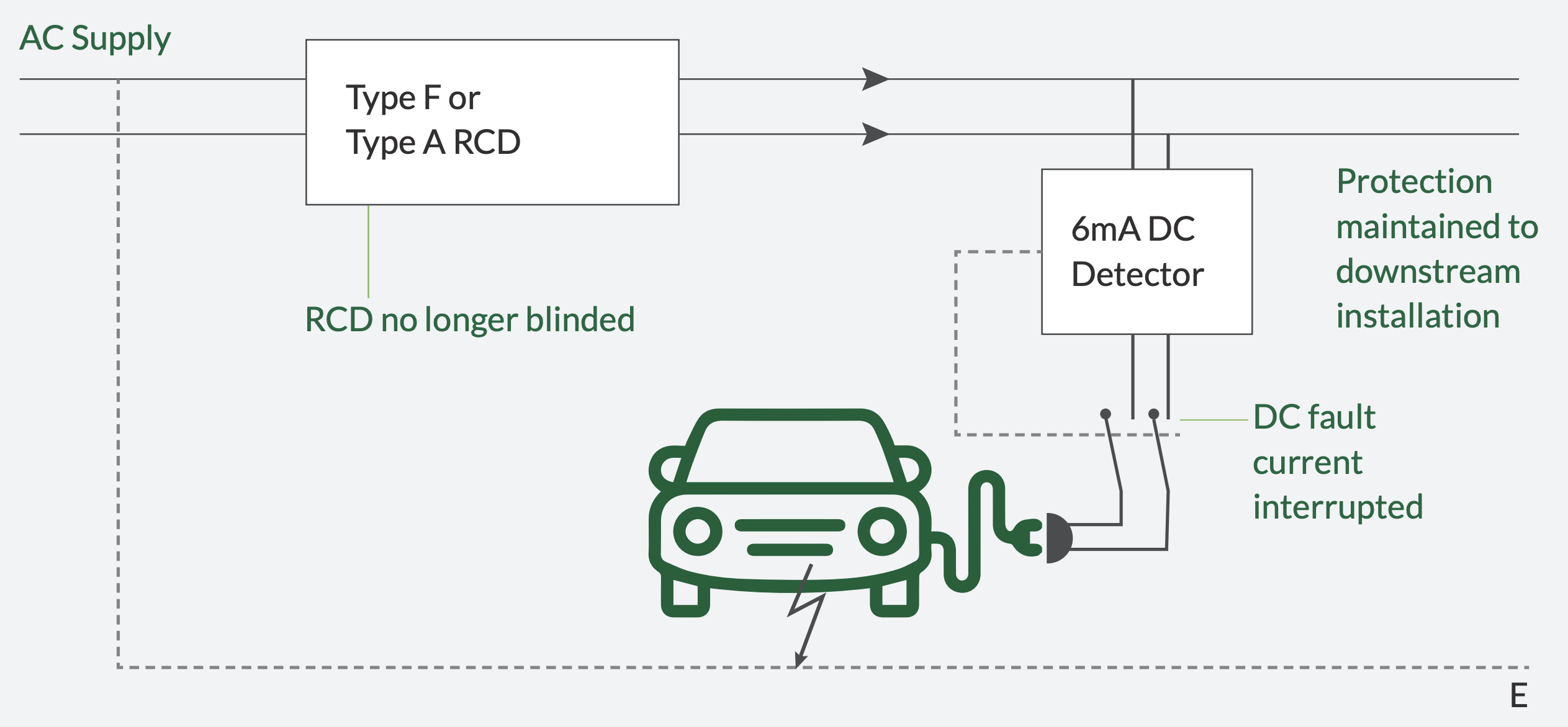
Figure 5: RCM14-01 adds monitoring of DC residual currents ≥ 6 mA to AC-sensitive Type-A RCDs in building electrical systems. (Image source: Littelfuse, Western Automation)
RCM14-03: 6 mA DC/30 mA AC RCM module according to IEC 62752
The RCM14-03 is intended for use in ICCB or integrated protection devices for EVs in charging Mode 2 to interrupt the supply.
RCM14-04: 56 mA DC/20 mA AC RCM module according to UL 2231-2
The RCM14-04 module detects AC and DC fault currents in 60 hertz (Hz) AC installations. It is designed for use in Charging Circuit Interrupting Device (CCID) EV charging station applications.
RCM20-01: The RCM20-01 is a residual current monitor intended for the detection of DC residual currents in 50 Hz/60 Hz AC installations. The product is fully compliant with IEC 62955.
RCM20-03: The RCM20-03 is a residual current monitor intended for the detection of DC and AC residual currents in 50 Hz/60 Hz AC installations. The product is fully compliant with IEC 62752 and can also be used for IEC 62955 applications where 30 mA AC fault detection is required.
For integration in a larger device circuit, the following RCM modules presented are also available as open-frame systems:
Each system consists of a solderable sensor pc board and a separate current transformer (Figure 6).
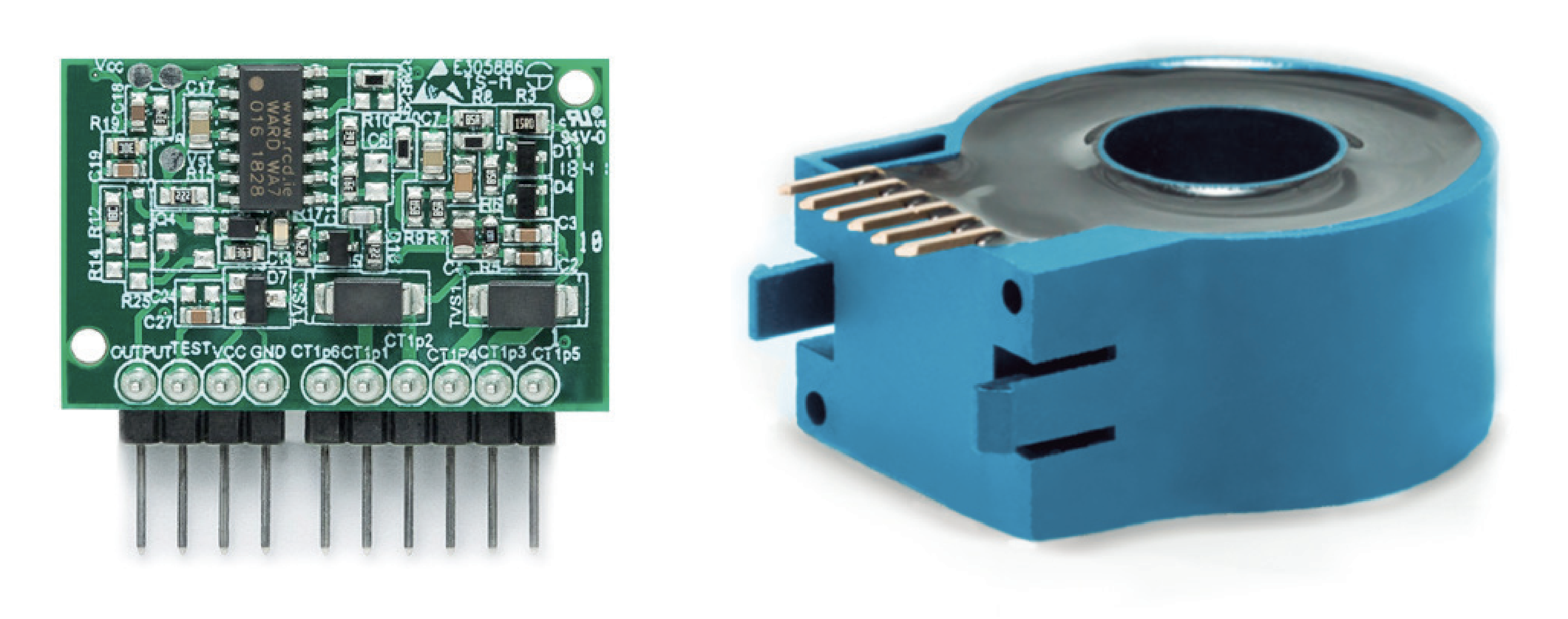
Figure 6: The RCM14-04_SYS modules are open-frame systems consisting of a sensor pc board and a current transformer. (Image source: Littelfuse, Western Automation)
Conclusion
AC-sensitive Type-A RCDs are common installation standards in building electrical systems, but they cannot protect against DC residual current hazards in EV charging circuits. As shown, the RCM14 series can perform the DC residual current monitoring required in ICCB charging cables (Mode 2) and EV charging stations (Mode 3). Featuring only four connection pins, system designers can easily and cost-effectively implement the compact RCM module or the open-frame system in their EVSE.
The original article can be found on the DigiKey website.