


What is a signal generator?
Signal generators (or sources) provide precise, highly stable, and customisable test signals for a variety of components and sub-systems that emulate real-world scenarios. The outputs can be anything from a simple continuous wave to more complex modulated digital signals. Signal generators are an essential part of product development because they allow the application of signal impairments for testing a product in various conditions within and beyond design limitations.
Form factors
Signal generators can be classified based on their form factor and capabilities. The most common signal generator form factor is a benchtop. Typically, these instruments sit on a workbench or in a rack. These instruments provide a single function and cannot be expanded.
PXI Express (PXIe) modular form factor signal generators are compact instruments housed in a PXIe chassis and controlled using a PC. Multiple PXIe signal generators are in a single chassis, making them great for applications requiring multi-channel measurements and a compact footprint. PXIe sources are configurable with a mixture of analogue and vector signal generators. They can also give the flexibility of having multiple inputs and outputs by adding a vector analyser to the chassis.
Classifications
Analogue signal generators supply sinusoidal continuous wave (CW) signals with optional capabilities to add AM, FM, phase, and pulse modulation. Vector signal generators (VSG) enable complex digital modulation schemes such as quadrature phase-shift keying (QPSK) and 1,024 quadrature amplitude modulation (QAM). There are also agile signal generators that are speed optimised, which can quickly change the signal’s frequency, amplitude, and phase. Lastly, there are vector signal transceivers (VST) that combine a vector signal generator with a vector signal analyser giving the power to create a signal and analyse a device under test with one instrument.
Playback modes
Playback mode options are only relevant to vector signal generators. Arbitrary waveforms and real-time waveforms are the two options for generating signals. Both allow for testing and validating, but choosing one depends on the application and purpose. Arbitrary waveforms are shorter samples or predefined signals stored on a signal generator. This feature means a signal generator must have enough memory for the sample. Alternatively, a real-time waveform generator relies on software to generate the signals for testing. This function removes the need for the signal generator to have an internal memory to store waveforms.
A good example of playback modes is the testing of a Global Navigation Satellite System (GNSS) receiver. A GPS almanac is a requirement to start the process of locating satellites. Storing this on a signal generator would require a significant amount of memory – a real-time generator would be the best choice. Whereas testing a local oscillator (LO) does not require a generated signal that lasts for an extensive period.
Accessories
One signal generator cannot meet every need – accessories added to a source can bridge functionality gaps. Frequency extenders can add to the range to a signal generator beyond what it can naturally produce for specific testing requirements. There are also digital signal interface modules that give a user access to a source’s digital inputs and outputs.
What affects accuracy?
A signal generator’s amplitude accuracy, frequency accuracy, spectral purity, and error vector magnitude (EVM) measurement are key sources of error. Many attributes determine the signal generator’s accuracy and preciseness, and knowing where to look for errors is essential.
Amplitude accuracy
Amplitude accuracy compares the proximity of the signal generator’s output to the desired amplitude set by a user. Consider the example of frequency sweeping to test filters and power amplifiers. Choosing a signal generator with a tighter amplitude frequency specification provides a more uniform output across a frequency range. Figure 1 illustrates the flatness of a signal generator when determining the amplitude accuracy across a group of frequencies.
.jpg)
Figure 1. Amplitude accuracy of a source across the frequency range
Temperature range and amplitude accuracy
An extra factor that affects amplitude accuracy is temperature. Characterisation by a specific frequency and temperature range determines the accuracy of a device. Temperatures outside of this range cause an accuracy roll-off. If the signal generator’s ambient temperature is outside the defined range, it is essential to check whether the temperature difference will affect the amplitude accuracy. Figure 2 is an example of temperature specifications of a signal generator. The footnote gives the temperature range and degradation for temperatures beyond that range.
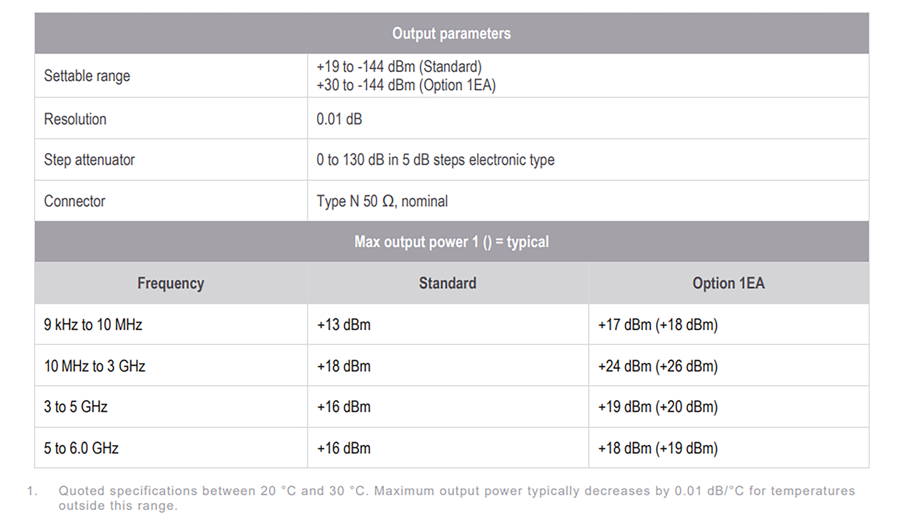
Figure 2. An example of amplitude specified within a temperature range for a signal generator
Frequency accuracy
Two key factors for understanding the accuracy for frequency generation are the stability of the reference oscillator and the time between source calibrations. The time between calibrations is also known as the ageing effect or rate. Frequency accuracy is vital to RF applications, especially where bands have data that are closer together. For example, in wireless communication, it is important to understand how well a receiver can process a signal while rejecting the signal from an adjacent channel. Poor frequency accuracy will cause the signals to be too close or too far and give a misleading indication of the performance of the device under test (DUT).
The ageing rate and frequency
The ageing rate indicates how fast the reference drifts from its specified value after calibration. The rate uses the parts-per-million (ppm) unit of measure. An oscillator is a primary component of where ageing comes into play. A quartz crystal’s physical properties within an oscillator exhibit a gradual change over time, resulting in frequency drifting. The ageing of a crystal is ongoing and requires that a signal generator keeps to a calibration maintenance schedule.
Spectral purity
An ideal signal generator produces a sinusoidal wave at a single frequency without the presence of noise. In the real world, every signal generator has unwanted amplitude and phase impurities added to the signal. This is due to the non-ideal components used to create the signals. A visual representation for the components of a signal can be seen in Figure 3. The characterisation of spectral purity evaluates harmonics, sub-harmonics, spurs, and phase noise.
Regardless of signal stability, it is important to choose a signal generator with better spectral accuracy than the DUT. This prevents the measurement of the signal generator’s performance versus the DUT. In datasheets, it is common to see the spectral purity represented as the single-sideband (SSB) phase noise.
- To understand the characteristics of spectral purity it is helpful to know that:
- Phase noise is a frequency-domain view of the noise spectrum around the oscillator signal. It describes the frequency stability of an oscillator.
- Harmonics and sub-harmonics are integer multiples of the sinusoidal fundamental frequency output. Nonlinear characteristics of components in the signal generator cause harmonics.
- Spurs are non-random or deterministic signals created from mixing and dividing signals to get the carrier frequency. These signals can be harmonically or non-harmonically related to the carrier.
- Broadband noise floor is the added unwanted noise produced by the non-ideal components of a signal generator. Noise floor magnitude can vary across frequencies.
- Continuous wave (CW) is the desired frequency set to a specific amplitude. Users select and modify the CW as needed.

Figure 3. Various non-ideal spectral components
EVM measurement
Figure 4 represents the error vector magnitude (EVM) difference between the ideal reference signal and the measured signal at a given time. This result defines the performance of a digital radio transmitter or receiver. Signal generators with smaller EVM percentages enable users to design and test systems to reach higher data capacity and better power efficiency while increasing wideband signal power.
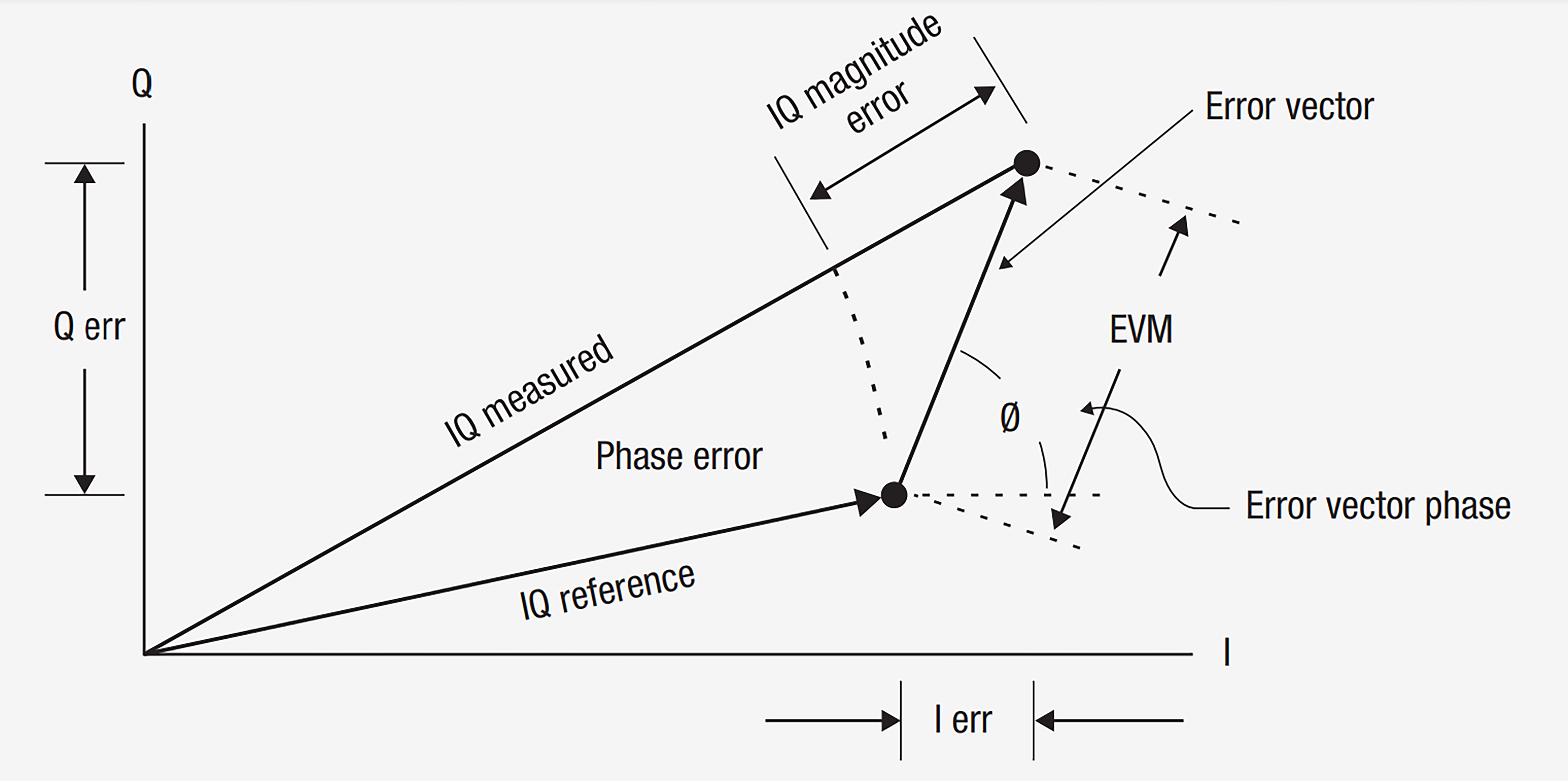
Figure 4. EVM is the difference between the actual measured signal and the ideal reference signal
The impact of distortion on performance
Distortion is an alteration of the original waveform. There are two major types of nonlinear distortion in signal generators: harmonic distortion and intermodulation distortion. Harmonic distortion happens when a smooth voltage change of a pure sinusoidal wave incurs an interruption caused by an abrupt voltage change. Intermodulation distortion is a spurious output that occurs when mixing two or more signals with different frequencies.
Spectral regrowth is the distortion generated by amplitude and phase shifts in digital modulations. Spectral regrowth spreads outside the main channel, and adjacent channel power ratio (ACPR) measurements examine this characteristic. Similar to spectral purity, it is important to choose a signal generator with a superior distortion test margin so that it does not mask the performance of the DUT. Knowing this type of digital distortion is becoming increasingly important as wireless standards require more data throughput.
Conclusion
Understanding the fundamental sources of signal generator errors simplifies the process of narrowing down what instrument is right for each test project. When evaluating which signal generator to use, consider the ambient temperature a source will be in during testing. This will add relevance to the accuracy specifications in datasheets. In addition, have a plan for how often the single source will be recalibrated. Calibrating consistently is the best way to reduce the ageing effect. Lastly, evaluate the amount of EVM error and distortion from power the signal source naturally generates to avoid measuring the instrument’s performance. Collectively considering sources of errors leads to selecting a signal generator with the greatest signal purity for a task.