


You plug in the receiver under the dashboard and take your test vehicle for a spin, anxious to see how well the position it reports lines up with the roads on Google Maps. And, lo and behold, it doesn’t. At least not all the time. What did you do wrong? Or is the datasheet deliberately misleading?
Why we test using a best-case scenario
In fact, there’s a reason why a GNSS receiver’s performance on the datasheet tends to be better than its performance when deployed in a real world application, and there’s nothing shady about it. When we evaluate our GNSS receivers, we do everything we can to ensure that the performance and, in particular, any errors we observe are due to the GNSS receiver itself. After all, you expect the values in the datasheet to reflect the performance of the GNSS receiver and not to be tainted by sub-optimal testing conditions.
That’s why, to avoid any contaminating influences, we go out of our way to optimise our entire experimental setup. The result is a best-case scenario that is well beyond what you would find in commercial vehicles with built in GNSS receivers, let alone in vehicles equipped with an aftermarket positioning device.
To determine the value we put in the datasheet, we record and average a day’s worth of static position readings, made under favorable weather conditions. Although this clearly doesn’t represent the most common GNSS use cases, it offers the most accurate measure of the receiver’s performance.
Additionally, we test the performance of our receivers on the road to assess their accuracy in a more dynamic setting. In these tests, we position a high grade GNSS antenna on a flat and carefully dimensioned ground plate in the middle of the car’s roof and only use the highest quality RF cables with low attenuation to relay the satellite signals to the GNSS receiver, located inside the vehicle.
With this high end setup, we drive our test vehicle for hundreds if not thousands of kilometers in a variety of urban and peri-urban environments to collect GNSS signal measurements, which we analyse and compare in the lab to a ‘truth’ reading obtained using a very high-end (and expensive) PVT setup. While any imperfections in our setup may still contaminate the accuracy values we report to our customers, we will have done everything in our power to quash them out in our tests.
The many constraints of real world applications
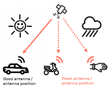
Back to the OBD dongle. In all likelihood, it uses a built-in, passive GNSS antenna with limited gain. Obviously, when in action, it will be anything but static. Rather than being located on the car’s roof, in direct line of sight of orbiting satellites, its standard-grade antenna will probably be stashed away somewhere beneath the dashboard, forcing the already weak satellite signals to penetrate additional layers of metal and plastic (as well as, perhaps, a thick cloud cover) before they are picked up by the device.
Furthermore, due to cost constraints, the wiring used to connect the GNSS antenna and the receiver is unlikely to be as high end as the wiring we used in our test setup.
Now that you are armed with a better understanding of why it is unrealistic to expect the actual performance of a GNSS receiver to match the performance reported in the datasheet, you might be wondering: Given the real world constraints that your product is subject to, what can you do to improve performance without breaking the bank? It’s a concern that we’ve taken very seriously, and it’s why we added a new feature to the u‑blox M9 GNSS receiver platform: weak signal compensation.
Performance test in dynamic scenario with a weak antenna setup
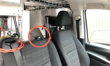
To assess the performance of our latest generation of standard precision (single band) GNSS receivers, we ran a series of tests in which we mimicked weak signal conditions that are common in real world applications by mounting the GNSS antenna inside the vehicle in between the front seats.
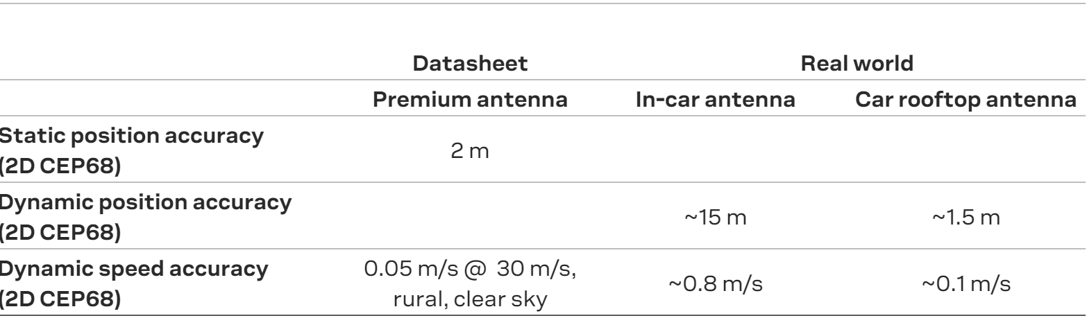
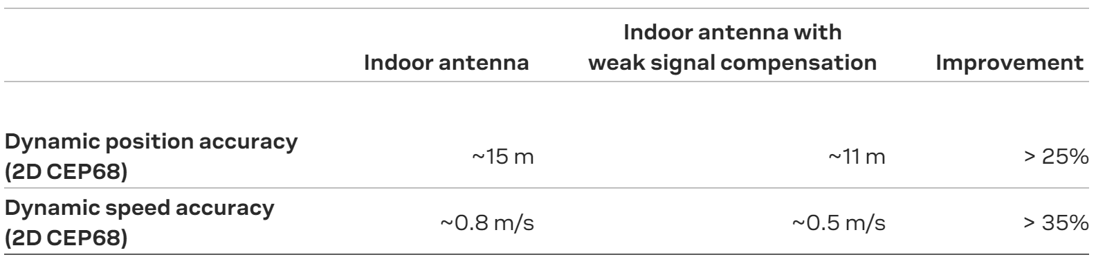
In the table below, we compare its performance in terms of accuracy and speed with the performance of the roof-top antenna and the datasheet figures. The difference is significant (and because of a statistical fluke, our dynamic position accuracy actually beat the datasheet value).
Then we compared the performance of the ‘real world’ scenario, which consisted of a drive in and around Zürich, Switzerland, both with and without weak signal compensation. Whereas signal attenuation hardly impacts the performance of GNSS receivers with a rooftop-mounted antenna, whether in urban or peri-urban scenarios, it considerably improves the position and speed accuracies measured using GNSS receivers with in-car antennas, as the table below shows.
Comparing apples with apples (and giving them an extra shine)
Hopefully this blog post will have helped to clarify why, in most real world scenarios, GNSS receives fail to live up to the accuracies reported on the datasheet. Using a high end test setup to qualify receiver accuracy is a standard practice in the industry. Far from being misleading, it lets you compare apples with apples when sourcing the hardware you need for your solutions.
By improving position and speed accuracies by over 25% in real world scenarios, u‑blox M9’s unique weak signal compensation feature will help you push your application’s performance closer to the datasheet values. To learn more about how weak signal compensation can improve the performance of your product, contact your nearest sales representative or field application engineer.
Guest blog written by Bernd Heidtmann, Product Manager, Product Strategy for Standard Precision GNSS, u‑blox
Courtesy of u-blox.