


Regenerative braking techniques provide highly controllable and energy efficient (not to mention compact) alternatives to friction clutches and brakes. In short, the circuitry involved in regenerative braking converts the dynamic mechanical energy from the motor’s spinning rotor and any attached loads into electrical energy. The latter is then fed back into the power line for other use or dissipation.
First used in automotive applications in the early 1900s and in railway applications in the 1930s, the reclamation of motor energy was first termed regeneration with the first hybrid passenger vehicles – in which braking energy charges onboard batteries. Today’s regenerative braking industrial applications (and design variations) abound.
Top: Figure 1. VFD-EL multi-function drives run ac motors with high-precision current control. A common DCbus simplifies side-by-side installation and most VFD-EL drive models can connect in parallel gangs to share regenerative braking energy. That in turn prevents overvoltage and stabilises the DC bus voltage. (Image source: Delta IA)
1. Dynamic braking: Sometimes called regenerative resistor braking it is one form of regenerative energy use – though differing from what is termed true regenerative braking. Here the system’s drive (also called an inverter for its defining function) dissipates the motor rotor’s rotational energy through heat waste to fully brake the motor – and nothing more. For example, a motion axis on an automated piece of machinery might suddenly turn off while its electric motor is running. Usually system friction is low enough to let the rotor coast, which is by definition out of control.
Coasting continues until kinetic energy is expended, which can take quite a long time – and poses a risk of machine damage or personnel injury in the meantime. Dynamic braking addresses this problem by bringing motors to faster stops through the conversion of rotor kinetic energy to electrical energy. The latter is performed by voltage-regulated resistors that in turn shed the energy as heat.
Many motor drives – especially digital servo amplifiers – have built-in resistors for such heatsink energy dissipation. However, if the motor-driven axis sees regenerative energy exceeding the drive resistors’ combined rating, external regenerative-resistor banks may be necessary. That’s fairly typical on axes exhibiting large load-to-motor-inertia ratios.
Where a regenerative braking system employs an external add-on brake resistor, the latter usually connects between the motor-drive terminals; system tuning software can then detect and profile the add-on resistor and its heat-shedding capabilities. A common resistor format is one with an aluminium housing filled with material of high thermal conductivity for quick thermal dissipation. Speedy shedding of heat is especially important for continuous braking applications.
2. Regenerative braking: Differs from dynamic braking in that it feeds mechanically generated electrical energy back to the main power supply or the common DC bus to keep the regenerative energy for:
- Reuse in braking.
- Re-actuation of the braked axis.
- Powering other axes on the system.
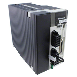
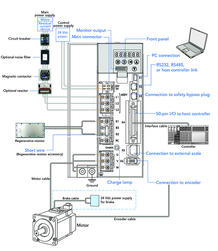
Above: Figure 2. This MDDHT5540E servo drive includes a built-in regenerative resistor to allow for regenerative braking. (Image source: Panasonic Industrial Automation Sales)
Sometimes called line regen units, most regenerative braking systems in industrial automation employ insulated-gate bipolar transistors (IGBTs) to allow bidirectional flow of power between the motor and power source, which is impossible with traditional inverter bridges using diodes. Note that this use of IGBTs contrasts with some of today’s electric vehicle applications based on traction drives. In some instances, SiC-based devices can convert DC power into three-phase AC power to drive the motor (and then regenerative braking energy back to DC for battery charging) with more efficiency and power density than IGBTs and other MOSFETs.
Because regenerative braking transforms the motor-rotor mechanical energy to electrical energy, it effectively makes the motor work as a generator in quadrant two and four of the motion-control speed-torque plane when commanded torque and rotation are in opposite directions. This is when:
- The axis command reverses and the rotor briefly continues to turn in the opposite direction.
- The rotor speed exceeds the motor’s commanded synchronous-speed output.
There are caveats when integrating regenerative braking into an automated design. Regenerative braking can slow but not stop and hold loads. As the axis nears a complete stop, there’s little energy remaining to excite the (motor acting as) generator. So, without some additional brake or electronics, the rest of the slowing to stop is done through coasting. In addition, there are limits to how much energy can be fed back into standard DC-bus capacitors before triggering an overvoltage fault. So well-specified regenerative drives return a sufficient amount to the AC power source – or make use of specially engineered common busses. Because the latter converts power from AC to DC only once before the energy sees reuse by a drive, they’re particularly efficient.
Another portion of a VFD that can be specially tailored to regenerative braking includes the rectifier. Variations called active front-end rectifiers minimise harmonics on system current. Consider the AFE2000 series active front-end from Delta Electronics that does away with traditional braking resistors by converting excess energy into reusable power to go back to the mains. AFE200 front ends are designed for a wide range of applications to maximise energy efficiency. This and other drives capable of regenerative functions also resolve a wide spectrum of harmonic distortions on the system current (especially at low power) to in turn protect nearby electronics (such as those for control feedback) from EMI.

Above: Figure 3. This BA-series BAB116025R0KE aluminium housed brake resistor is suitable for high-power regenerative braking applications. (Image source: Ohmite)
3. Injection of DC current for electric-motor braking (in certain contexts simply called DC braking) includes drive electronics that put DC current onto one or two of an AC motor’s windings. No matter the exact variation, most DC-injection systems are triggered into action when a relay or other control switches off the motor’s rotating magnetic field. Then another relay or electronic braking control (within the drive for VFDs) triggers the supply of DC power from the system’s DC bus to the motor windings. Higher current induces more braking force, though these components control applied voltage and keep current into the windings to below the motor’s maximum ratings.
The result of DC injection is a non-rotating electromagnetic field from the stator that stops and holds the rotor (and any attached loads) in place.
The main limiting factor of DC-injection braking is how much braking induced heat a motor and its associated electronics can dissipate without sustaining thermal damage. That restricts the magnitude and length of time that braking current can be applied. No wonder that DC-injection braking is rarely used to hold loads or serve as fail-safe brake systems. To prevent overheating in some DC-injection systems, zero-speed sensors can cut power as soon as it’s clear the rotor has stopped rotating.
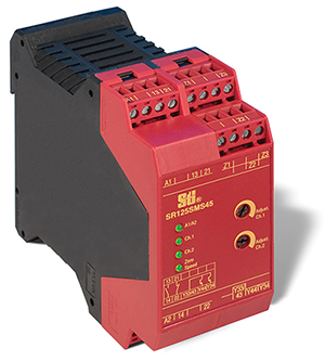
Above: Figure 4. Shown here is an Omron SR125SMS45 stop-motion safety relay that tracks when connected motors have come to a complete stop. (Image source: Omron Automation and Safety)
Choice and combinations
Most designers can leverage the efficiencies of regenerative power during one or more regular operations. However, regenerative braking in automated machinery is most useful on specific motor-driven axes.
Dynamic braking (based on cost-effective braking resistors) is most suitable for low-duty automated axes needing occasional braking or reversals.
Regenerative braking is suitable for automated axes needing:
- Frequent stops and starts.
- The actuation of overhauling loads that cause rotor rpm to exceed the motor speed – as on elevators and incline conveyors.
- Continuous-duty applications (including those that require frequent enough operation to qualify as constant duty).
- Systems for which the energy savings can justify the additional upfront cost of a regenerative drive.
As explained above, DC-injection braking can be applied alone. However, it’s often more common for DC-injection braking to be combined with regenerative or dynamic braking. That’s because DC-injection braking assumes the braking function where regenerative braking peters out; when the axis nears its stop and requires holding. Dual-system braking arrangements such as these leverage multiple technologies’ strengths for true high-performance electronic braking presenting little risk of overheating.
Application examples
Regenerative braking is a useful approach to slow and control an array of moving loads while reclaiming their kinetic energy for other system use. Increased focus on energy efficiency has prompted design engineers to employ regenerative braking where applications present the best opportunities of potential energy reclamation. These include designs involving:
Vertical axes for lifts, cranes, and elevators: For example, lowering hoisted loads without counterweighting involves the force of gravity and the torque of the motor for a safe and controlled descent. It’s key in these situations that the braking system works well even if main power is cut. Otherwise, the kinetic energy will have no outlet – and the axis will enter a free-fall or runaway condition. In other instances, a backup or emergency generator (with its own design requirements) may be used. Upon switching to generator power, most systems temporarily disable their drives’ energy reclamation functions.
Spinning centrifuges, test stands, and fans: Many of these designs are constant duty cycle axes necessitating the external add-on brake resistors mentioned earlier.
Web tensioning and web processing: Here, AC induction motors (paired with VFDs capable of regenerative braking) are common. That’s because such motion designs deftly handle high-speed high-inertia axes of printing presses as well as paper and plastic spool processing.
Rapidly accelerating and reversing axes: Regenerative braking helps make these motions more efficient on advanced conveyors, saws, and heavy robotics. That boosts the effectiveness of VFD-based operation matching rotor speed and torque to application demand and helps quickly halt high-rpm axes so common in servo applications.
Above: Figure 5. Panasonic’s servo drives combine advanced technology with a wide 50W to 5kW power range. (Image source: Panasonic Industrial Automation Sales)
Conclusion
Understanding the differences between DC-injection braking, dynamic braking, and regenerative braking is key to specifying the appropriate technique for a given axis. It’s also helpful in selecting electric motors and drives capable of accepting and delivering speed and torque control through these methods. Dynamic braking is typically quite suitable for moderately demanding axes necessitating some braking; in contrast, regenerative braking complements very dynamic axes and critical functions on automated (and even servo) machinery. Systems for current injection are most commonly employed in conjunction with these other methods.
