
Current sensors for isolation in high voltage systems
Any item of equipment that incorporates high voltage control components and a user interface has to be designed with safety clearly in mind in order to protect users from electric shock. This involves equipment meeting isolation standards through the use of insulation layers. Most standards require the user to be protected from electric shock by two levels of protection or a single layer of reinforced insulation protection. Shaun Milano of Allegro MicroSystems explains.
This article discusses the various types of insulation and how they comply with international standards for voltage isolation, using the design of a variable frequency drive as an application example. In particular, it shows how innovative Hall effect current sensor packages can be used to achieve high isolation ratings that meet industry standards.
Introduction
In this article, a variable frequency drive is used as an example of a system that must meet isolation standards through the use of insulation layers. Many of the isolation concepts described will apply to almost any system that has high voltage control components and a user interface.
The basic assumption is that all equipment should be designed with safety clearly in mind to protect users from electric shock. Most standards require that the user be protected from electrical shock - either by two levels of protection or by a single layer of insulation protection that is considered to be ‘reinforced’ as defined in the following list:
- Basic insulation: Insulation to provide basic protection against electric shock.
- Supplementary or supplemental insulation: Independent insulation applied in addition to basic insulation in order to reduce the risk of electric shock.
- Double insulation: Insulation comprising both basic insulation and supplementary isolation.
- Reinforced insulation: Single insulation system that provides a degree of protection against electric shock equivalent to double insulation under conditions specified by a standard.
The definition of reinforced insulation is a common cause of confusion for many system designers, as it requires familiarity with a safety standard. This need not be the case if the designer understands that only double or reinforced insulation is sufficient to protect a user against electric shock.
While there are many UL and IEC specifications which define a shock hazard voltage at slightly different levels, a good rule of thumb is any voltage exceeding 42.4 V RMS or 60V DC poses a risk. Lower voltages do not pose a serious risk for electric shock in most cases, and are referred to as extra-low voltage supply systems. For example, in the US, the telephone system, from its invention, was limited to 50V DC in order to protect users from electric shock and remains so to this day.
VFD architecture
These basic rules should be borne in mind when considering the architecture of the variable frequency drive (VFD) used as the application example.
A VFD will rectify an AC mains voltage to a DC voltage, and use that DC voltage to drive a motor. The designs shown in Figs. 2 and 3 (below) use a standard 3-phase VFD topology, with IGBTs used to switch the voltage to the phases of the motor. The IGBTs are controlled by the system microcontroller (MCU). The current feedback is provided by current sensors, and is also fed into the MCU, forming part of the motor control loop.
The VFD is controlled via a user interface that is normally connected to digital I/O pins of the MCU. The rectified voltage levels from DC positive to DC negative range from 200 to 1,000V DC.
While VFDs in this voltage range are considered ‘low voltage’ in terms of standard industry nomenclature, these voltage levels pose a serious risk of electric shock and require compliance with safety standards, generally involving double or reinforced insulation between the user interface and other electronics in the physical enclosure. This insulation is required to achieve the isolation rating for the standard to which it is certified, so that, when a device or system is certified, it is given an ‘isolation’ rating rather than an ‘insulating’ rating.
A common industry standard is UL60950-1 edition 2. While this standard was designed for information technology equipment, its stringent requirements have made it a benchmark standard for many different equipment and component designs. Common component level standards include IEC60747-5-2 and UL1577, and common system level standards beyond UL60950-1 also include 60730-1, 62368-2 and 61010-1.
Isolation solutions
Allegro has developed a number of current sensor IC solutions that provide the isolation required for VFD applications. These current sensors are implemented in fully integrated configurations, in which the current travels into and out of the sensor IC package on one side, and the signal leads are on the other. This set-up provides creepage and clearance between the primary current (high voltage) side and the signal leads (low voltage) side. An Allegro SOIC8 standard footprint IC is illustrated in Fig.1 (below)
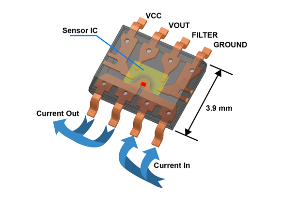
Surface mount current sensor ICs of this type can be used in any of the common sensing locations in VFDs, for currents up to 40A continuous, with peaks up to 65A or even higher, depending on the printed circuit board design. An applications note on package thermal performance for DC and transient currents is available on the Allegro website.
Flip-chip assembly technology provides spacing between the sensor IC and current carrying conductor in the package, which provides the insulation required to achieve high voltage isolation ratings under UL and IEC specifications.
VFDs require different isolation ratings depending on system architecture. Figs. 2 and 3 show two typical methods for achieving double or reinforced isolation in VFDs.
These configurations assume that the equipment is correctly wired and plugged into the AC mains and that the motor is properly connected and grounded safely so as not to introduce any further risk of electric shock. Under this assumption, it is possible to deal strictly with the insulation required between the user interface and the circuits inside the physical enclosure.
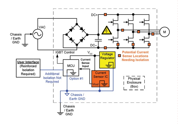
Option 1 (ground referenced)
In this configuration (Fig.2), the MCU is referenced to earth (GND), and the user interface would not normally be subjected to a voltage level that posed a risk of electric shock. The MCU would be provided with 3.3 or 5V nominal voltage from a regulator that is also referenced to GND.
Note, however, that the output signal of the current sensor is also connected to the MCU. The internal conductor of the sensor IC is therefore connected to dangerous voltage levels in the bridge driving the motor. If the user interface is directly connected to the digital I/O pins of the MCU, the current sensor IC is now required to provide double or reinforced isolation as the only means of protecting the user.
Wherever the current is sensed in Fig.2, the use of a chassis or earth ground topology means that the current sensor will need to provide reinforced isolation. The reason is that, if the current sensor were to fail, the MCU would also fail and potentially expose the user to a shock hazard via the user interface.
Current sensor ICs similar to the example shown in Fig.1 and which are well suited for this topology, are available that provide reinforced isolation ratings up to 800V DC.
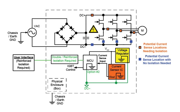
Option 2 (high-voltage referenced)
Another common VFD topology (Fig.3) has the MCU referenced to a high voltage potential, either the negative or positive DC rectified voltage. The user interface would therefore also be exposed to this voltage potential if directly connected to the MCU, posing a risk of electric shock. For this reason, double or reinforced isolation between the user interface and MCU circuit is required for protection, as illustrated in Fig.3.
Since double or reinforced isolation is required between the MCU and user interface, the current sensor only needs to provide functional voltage isolation to protect the MCU. This is easily accomplished with the basic insulation available in many Allegro current sensor ICs - although, with this topology, some sensing locations do not require any isolation, as shown in Fig.3, through being at a similar potential to the MCU.
Finally, as previously mentioned, the user interface to the MCU in a VFD is generally composed of simple digital I/O lines, so the reinforced insulation is provided by digital or opto-isolators with a reinforced isolation rating. Every I/O pin between the MCU and the user interface requires this protection, and therefore several opto-isolators may be required. By employing the ground referenced topology of Fig.2 with reinforced Allegro current sensor ICs, the opto-isolators can be removed - however, the MCU then needs to be isolated from the drive signals to the IGBTs.
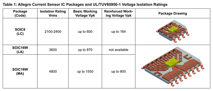
No matter which VFD topology is used, there are several patented technologies developed by Allegro that achieve either basic or reinforced isolation in small footprint current sensor semiconductor packages to meet the application needs. A diverse portfolio of current sensor ICs is available from Allegro for VFD (and other high voltage) applications with different integrated features and accuracy levels. Each of these patented current sensor ICs is certified to stringent industry standards, such as UL/TUV 60950-1 and UL1577.
Table 1 (below) summarises the surface mount package options available and their associated standard certified isolation levels. All components in Table 1 are certified to the IEC/UL60950-1 specification. The summary table includes options for a standard SOIC8 package footprint and a wide body SOIC16 package footprint. The different isolation ratings are derived from internal or external construction techniques that were designed to comply with the UL or TUV specifications used to certify the ICs. Note that all these packages provide a basic isolation rating that enables high operating voltages. Devices in the SOIC16 wide-body (MA) package can provide a reinforced rating on DC buses as high as 800V DC, and a basic rating up to 1,550V DC.
Product Spotlight
APV1111GVY
Panasonic

Panasonic PhotoMOS® Photovoltaic MOSFET High-Power Drivers
| SKU: | |
|---|---|
| Stock: | 3490 |
| Cost: | $3.95 |
