


Quantum computing is gaining attention for its ability to solve complex problems that prove difficult for regular computers. In this journey, instruments like the DC bias source play a crucial role, especially for flux-tuneable superconducting and silicon spin qubits. The DC bias source helps to adjust the flux to decide the resonance frequency of the superconducting qubit and to apply DC bias voltage to each gate terminal of silicon spin qubits. In addition, the number of qubits employed in a quantum computer increases the physical size of the machine based on the number of DC bias sources needed to control the qubits.
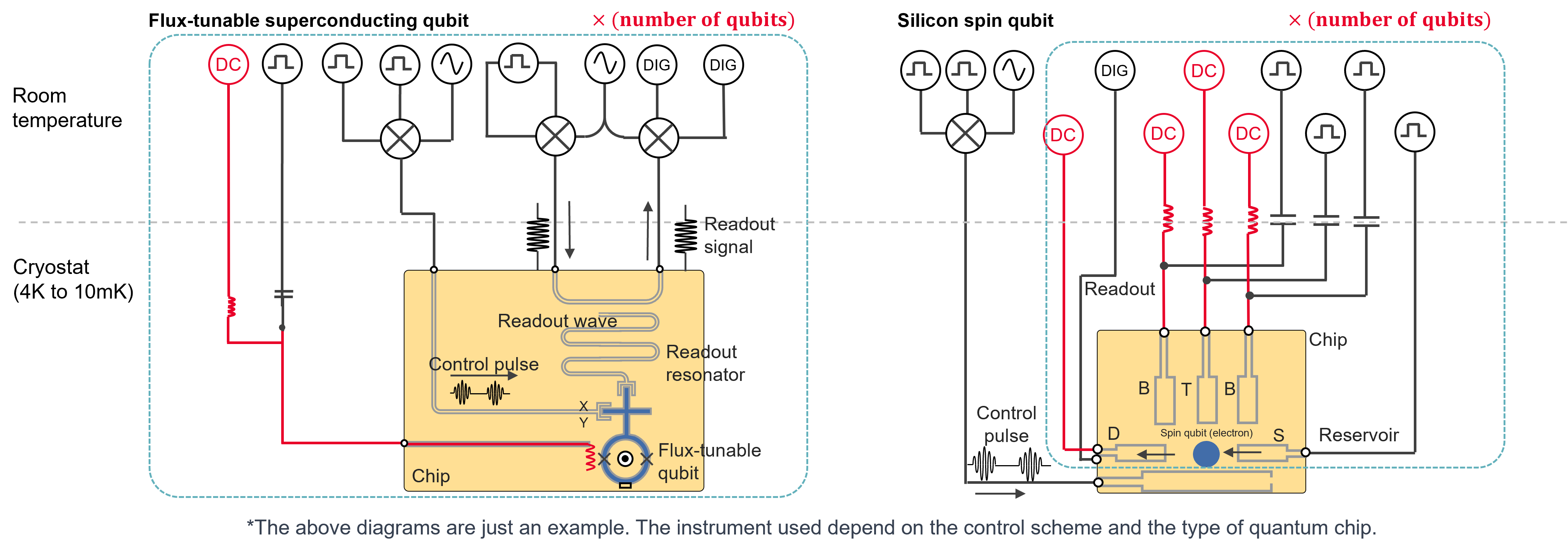
Figure 1. Single qubit control and evaluation system for flux-tuneable superconducting and silicon spin qubits. The instruments and lines indicated in red represent the DC voltage bias source and wiring. For the flux-tuneable superconducting qubit, the DC voltage bias source helps tune the resonance frequency using the magnetic flux generated in the coil. For the silicon spin qubit, the DC voltage bias source works by tuning the electric potential of gate terminals.
An engineer can initialise, control, and read the qubit states by using control evaluation systems, as depicted in Figure 1. This control evaluation system enables the characterisation of qubit properties like coherence time and fidelity and the execution of benchmark tests, thereby advancing the research and development of quantum computers.
Challenges in DC biasing of qubits
There are two significant challenges when using DC power supplies:
- Voltage fluctuations due to DC power supply noise and environmental interference through long cables induce qubit decoherence.
- DC power supplies that may number several hundred require substantial storage space and can introduce significant qubit decoherence.
Qubits are highly susceptible to noise and even minor voltage fluctuations. DC bias voltage can quickly induce unintended changes in the quantum state. These changes can lead to the loss of information stored in the qubit, a phenomenon known as decoherence. This results in a decline in the precision of qubit control and evaluation. Moreover, quantum computers have now reached a stage where they can exceed 100 qubits. It is essential to supply an independent DC bias to each qubit by securing substantial space to house several hundred general power supplies.
Voltage fluctuations induce qubit decoherence
In the quantum world, qubits exist in a superposition of states, representing both 0 and 1 simultaneously. This unique property makes them exceptionally powerful for certain computations. However, it also makes them incredibly sensitive to external influences. The challenge arises when DC power supply noise and environmental interference introduce voltage fluctuations that disturb the delicate balance of the qubit’s superposition.
Even the slightest variation in voltage can cause the qubit’s quantum state to waver, leading to decoherence making them less reliable for computations. This is a significant challenge in quantum computing because maintaining the integrity of qubit states is crucial for accurate and reliable quantum information processing.
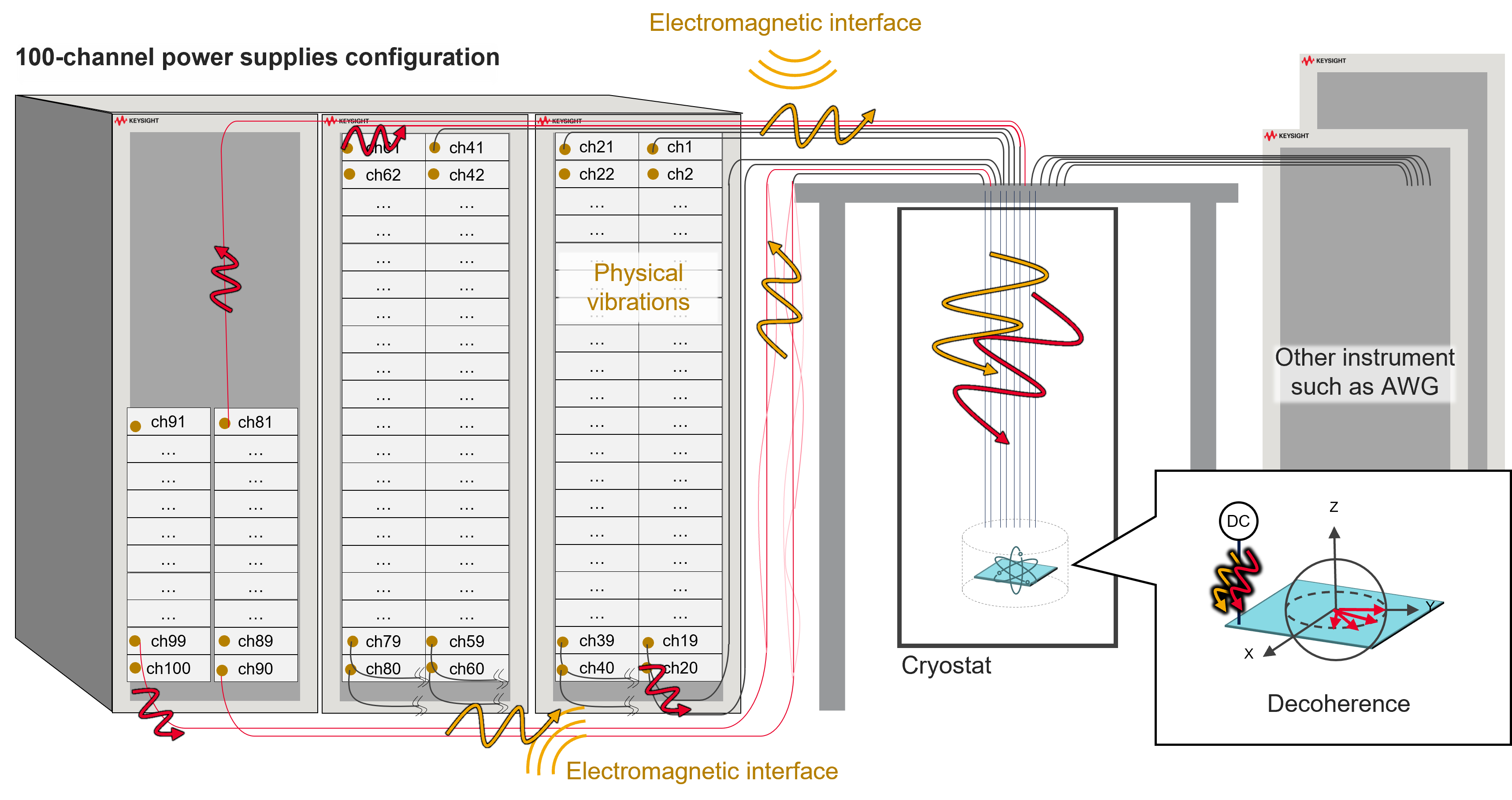
Figure 2. Fluctuation in DC voltage bias propagated to qubits
Fluctuations in DC bias voltage primarily contribute to the DC power supply’s output voltage noise. Furthermore, environmental interference, such as electromagnetic interference and physical vibrations of the cables, can contribute to voltage instability. The qubit’s sensitivity to noise necessitates continual monitoring of the potential noise source. Figure 2 illustrates how this effect becomes more pronounced when extending the cables because the DC power supply rack is at a distance from the entrance of the cryostat or if the power supply is in the lower sections of the rack.
The occurrence of voltage fluctuations disrupting qubit coherence is rooted in the fundamental nature of quantum systems. The challenge is not just about preventing external disturbances but also about developing tools and technologies that can shield qubits from these disturbances, ensuring stable and coherent quantum states for reliable computational processes.
Larger quantum computers can introduce more qubit decoherence
One important direction in the practical application of quantum computers is the increase in the number of qubits to run more complex quantum algorithms. For example, the current noisy intermediate-scale quantum (NISQ) machines under development require the implementation of tens to hundreds of qubits. This means the need for significant numbers of DC power supplies that both need to be physically stored and can introduce a lot of noise into the system.
This proliferation of DC bias sources introduces additional sources of noise into the system. The noise from DC bias sources can stem from several factors:
- Power Supply Imperfections: Not all power supplies were made for precision, and even small fluctuations or imperfections in the DC bias source can translate to noise in the qubit’s operation.
- Crosstalk: In a setup with numerous DC bias sources in close proximity, crosstalk can occur. This means that the adjustments made to one qubit’s bias source can affect neighbouring qubits, leading to unwanted noise.
- Electromagnetic Interference (EMI): The operation of multiple DC bias sources in a confined space can generate electromagnetic fields that interfere with each other. This interference can manifest as noise that disrupts the qubits’ quantum states.
As the number of DC bias sources increases to accommodate a larger number of qubits, the overall size of the system increases, and the cumulative effect of these noise sources becomes more pronounced. Each additional DC bias source adds another layer of potential noise, making it challenging to maintain the precision and coherence of the qubits’ states.
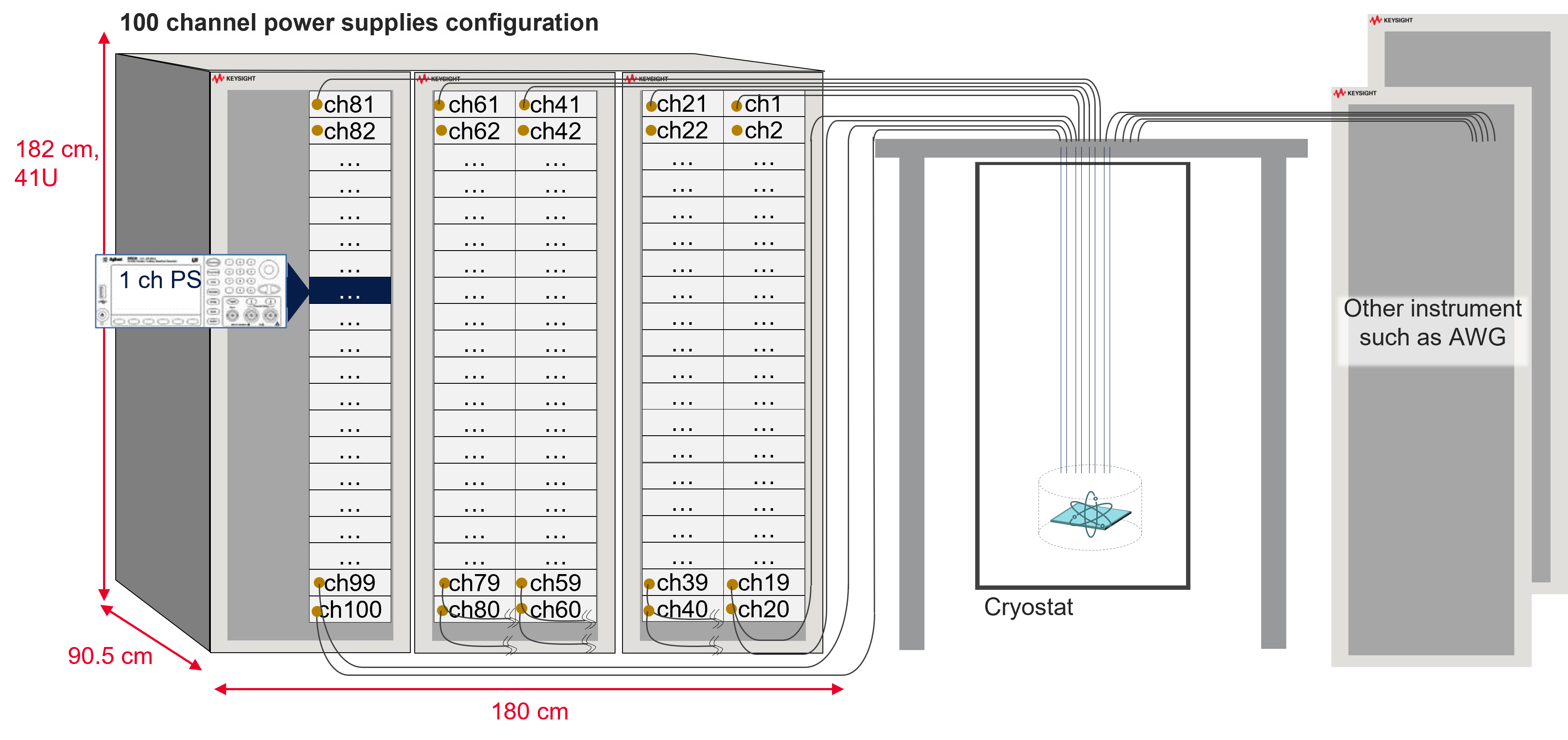
Figure 3. Configuration of 100-channel conventional precision power sources with a large footprint
Taking an example of a quantum computer that uses 100 qubits, providing DC bias voltage to each qubit presents an additional challenge. Figure 3 illustrates that each qubit requires at least one DC power supply. The test rack must fit in a minimum of 100 power supply channels to bias all qubits. Even with power supplies of a typical size 2U half-rack housed in a maximum-sized rack, a single rack can only store 40 channels.
Consequently, securing an ample space measuring 180 cm in width, 90.5 cm in depth, and 182 cm in height for three racks becomes necessary in a laboratory filled with various other instruments, such as arbitrary waveform generators (AWG). This necessity creates a logistical challenge regarding physical space within quantum computing laboratories. This spatial challenge not only impacts the physical layout of the lab but also raises practical concerns about efficient management, accessibility, and equipment maintenance.
There is a growing emphasis on developing compact and efficient power supply solutions that can cater to the individual requirements of each qubit while minimising the overall footprint to address this challenge. Streamlining the power supply infrastructure is crucial for the scalability of quantum computing projects, enabling researchers to expand their quantum systems without space constraints.
Enabling an effective and efficient quantum computing development
Solving spatial constraints helps scale quantum computing efforts, enabling researchers to explore larger quantum systems. Managing voltage fluctuations and spatial limitations in DC bias sources for quantum computing is crucial for progress.
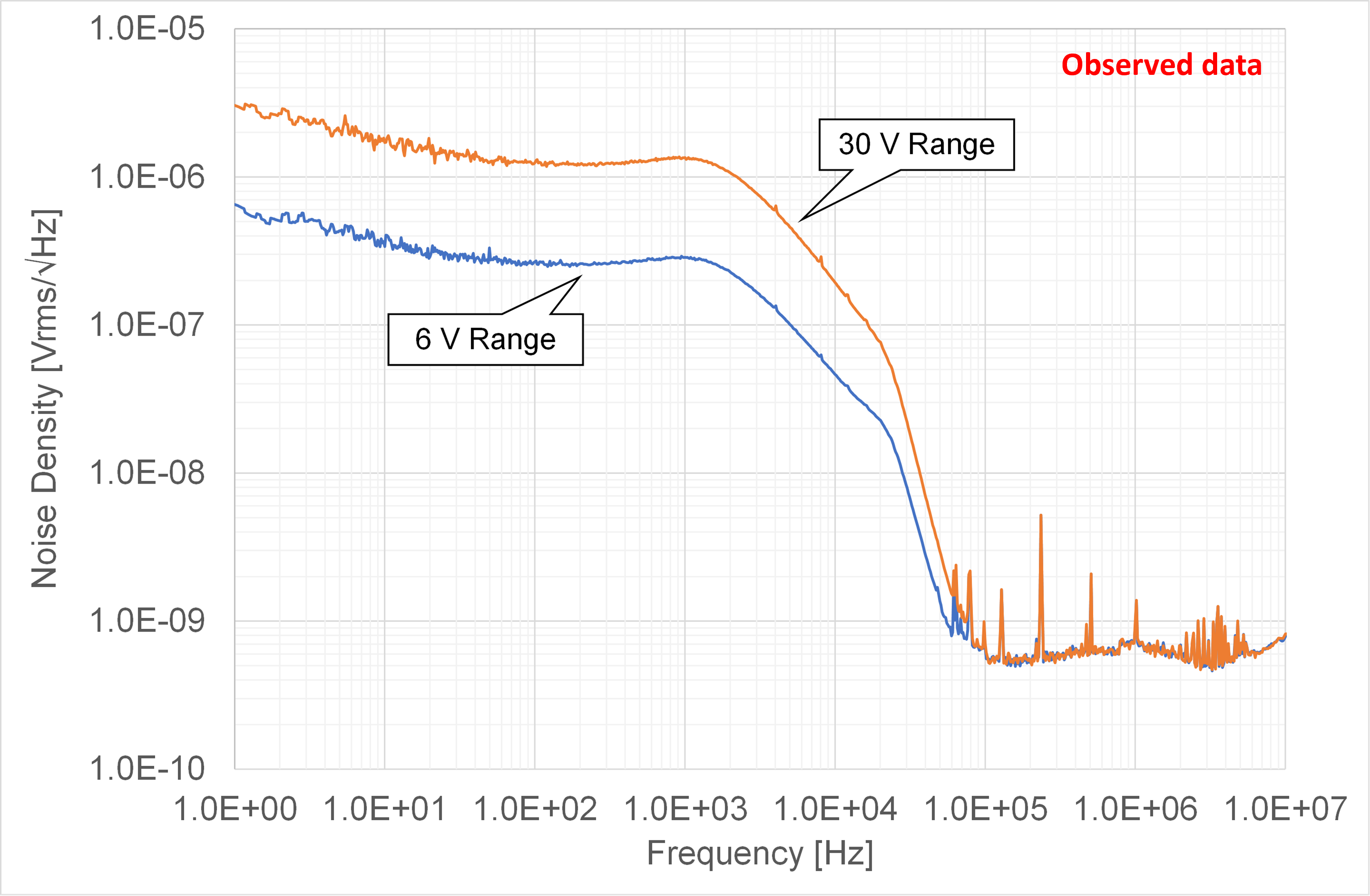
Figure 4. Voltage source noise density with the combination of a source metre and a low-noise filer adapter
It is essential to use low-noise power supplies or source metres / source measure units (SMUs) to provide clean bias voltage positioned as close as possible to the cryostat to achieve this. This approach can significantly help with unnecessary environmental interference caused by exposed cable lengths.
You can attach optional accessories, such as a low-noise filter adapter (LNF), to the precision source metres to further push the stability of the bias voltage. In some cases, reducing the noise level to 25 µV rms (10 Hz to 20 MHz, 6 V range) is illustrated in Figure 4.
Figure 5 shows, from a rack setup perspective, that using source metres that are as compact in channel density allows for placements directly at the entrance of the cryostat, even at elevated positions. This approach will significantly help to minimise the DC voltage bias fluctuation, enabling ideal quantum control and precise qubit characterisation through long coherence time.
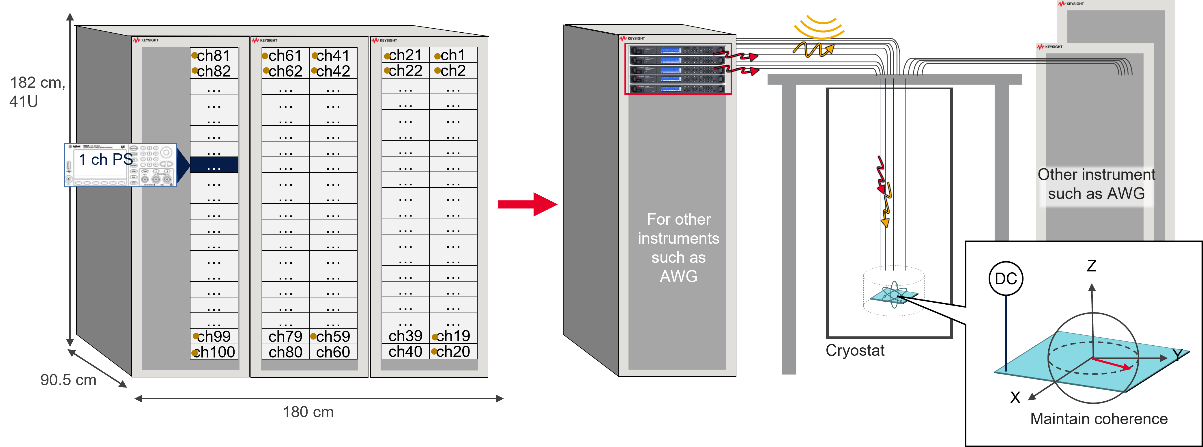
Figure 5. A 100-channel configuration with high-density source metres set close to the cryostat, providing clean DC bias voltage
Tips to minimise the fluctuations in the bias voltage
Given the significant impact of the surrounding environment and experimental setup on DC bias fluctuations, achieving a clean bias voltage requires proper setup and usage. When constructing your DC bias line, you can minimise voltage noise and effectively utilise a high-precision source measure unit and a low-noise filter by paying attention to certain aspects.
- Avoid ground loops: Using different grounds for each instrument can create a circuit known as a ground loop. Ground loops can be a source of noise. Figure 6 illustrates the steps to stabilise the DC bias voltage. Avoiding ground loops using techniques such as single-point grounding is necessary.
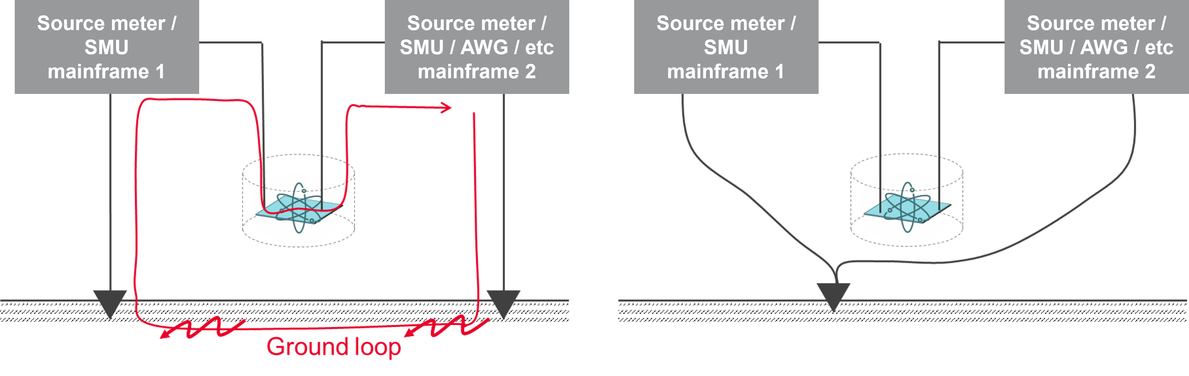
Figure 6. Examples of wiring that creates a ground loop (left) and avoids a ground loop (right)
- Choose the right LF terminal potential: You can either short the LF terminal to the frame ground or leave it floating. This choice could impact the noise level of the DC bias voltage. If your system design does not have specific requirements for the LF terminal’s potential, you can experiment with both configurations and choose the one that yields better results.
- Wire to minimise electromagnetic interference impact: According to Faraday’s law, electromagnetic induction can contribute to the noise if the HF and LF cables become spatially separated. To prevent this outcome, keep the HF and LF cables as close as possible or use a twisted pair configuration.
Conclusion
To solve these challenges, use a combination of source metre options that helps to provide a high channel density, low noise, and precision voltage supply to provide a stable and clean bias voltage to more than 100 qubits. Ensure the source metres are as close as possible to the cryostat to minimise electromagnetic interference from long cables. Always take note of the potential configurations of the LF terminal, avoid ground loops, and implement twisted pair configurations to reduce the impact of Faraday’s Law further.