


The semiconductor industry has set trends in current and future electronic devices, namely efficient power consumption, increasing load current, miniaturisation and higher switching frequencies. IC operation of the high-speed and large current increases variations in current load, and the low voltage operation comes to require very accurate stability in voltage. All require faster transient response for the converter to support the ICs. These trends encompass capacitors that can cope with higher current loads while at the same time the available volume is decreasing. Engineers have to balance between high performance and power density vs long time endurance, high reliability and safety.
The selection of a suitable I/O capacitor plays an important part in the design of switching voltage converters. 99% of so-called ‘design’ problems associated with linear and switching regulators can be traced directly to the improper use of capacitors. The importance of the output capacitor in switching DC/DC converters is related to the fact that it, together with the main inductor, is the reservoir of electric energy flowing to the output and it smoothes the output voltage. Some important considerations for input capacitors used in DC/DC converters are the power dissipation and ripple performance. To maintain the voltage and to make sure the rail voltage is stable to the converter, an input capacitor is required.
Capacitor types
Various capacitor types can be used in the input and outputs of DC/DC converters. Table 1 shows the types of capacitor and ranks their performance according to each characteristic. The application typically dictates the best choice of capacitor type (multilayer ceramic capacitor (MLCC), aluminum electrolytic, polymer, or tantalum) to use in the design. Generally speaking, while electrolytic capacitors provide the largest capacitance, they suffer significant degradation in capacitance and leakage current at higher temperatures and frequencies. Ceramic capacitors have a very low ESR and ESL that makes them suitable for transient performance but they have limitations on capacitance. Though ceramic capacitor can operate at very high ripple currents, they suffer the non-graceful aging failure and require lower operating electric fields. Polymer electrolytic capacitors are mainly used in power supplies of ICs as buffer, bypass and decoupling capacitors, especially in devices with flat or compact design. They compete with MLCCs, but offer higher capacitance values than MLCC, and they display no microphonic effect (such as class 2 and 3 ceramic capacitors).
MLCCs are the most widely used capacitor type in DC/DC converter input and output filters, due to their low ESR, low ESL and low cost. They also have no major reliability problems associated with them. There are, however, still some downsides to be considered when it comes to using these capacitor in DC/DC converters. They are characterised by a small capacitance per volume, especially for class 1 dielectric materials (NO/COG), they have large body sizes that are prone to cracking with PCB flex, DC bias instability and piezo-effect (singing).
This is where polymer capacitors can be considered. Conductive polymer aluminum solid capacitors (polymer capacitors), like conventional aluminum electrolytic capacitors, have large capacitance and good bias characteristics which MLCCs cannot compete with. In addition, polymer capacitors have extremely low ESR characteristics. ESL, which is determined by the interior structure and terminal configuration of the capacitors making structural improvements, is low in the polymer capacitors. Considering the dry-out of electrolyte in service life and the changes of characteristics at a range of low temperatures, the polymer capacitors have realised very high reliability and superior low temperature characteristics by using solid polymer materials as an electrolyte.
Polymer capacitors as alternatives to MLCCs
Panasonic’s SP-Caps and POS-Caps are the go-to replacement for MLCCs, due to their small size factor.
Figure 1 shows the change in capacitance over a wide frequency range for different technologies. It clearly shows that polymer capacitors exhibit very similar performance to MLCCs.
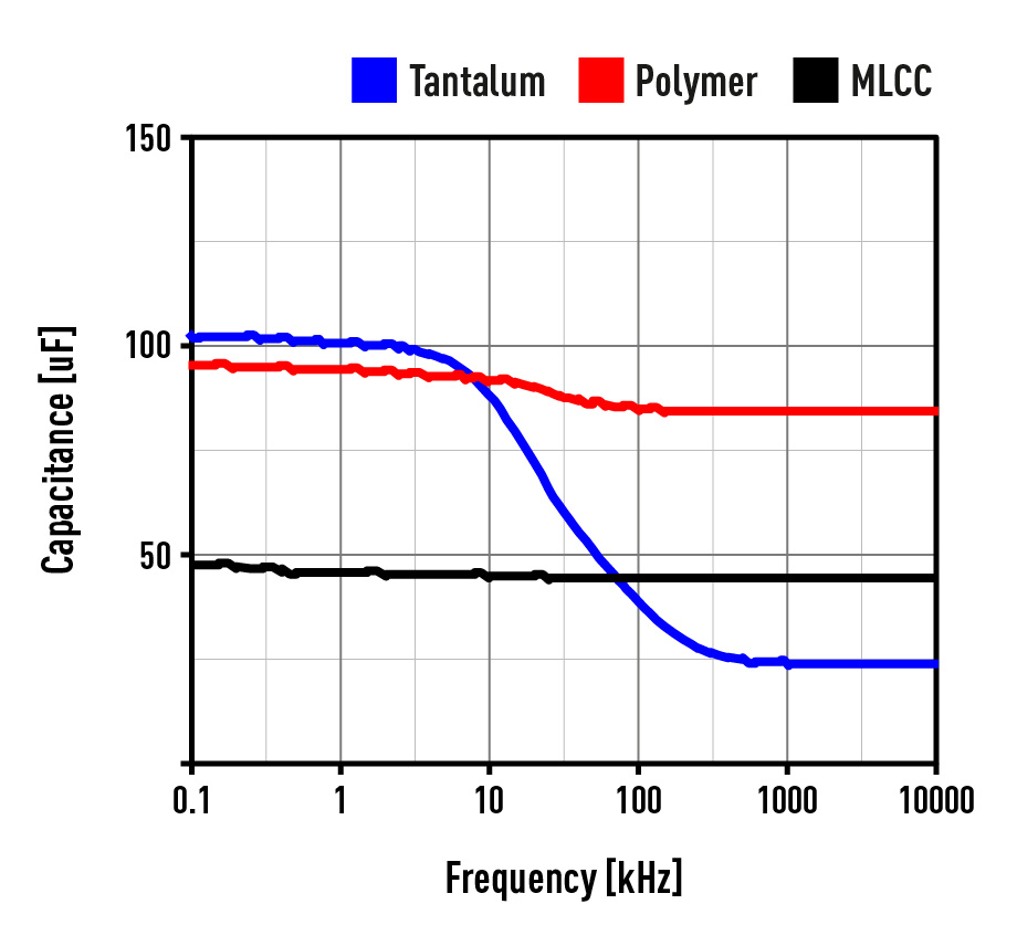 Figure 1: Capacitance variations according to voltage changes
This raises the question, why switch to polymer technology? The answer is that MLCCs cannot achieve the same high capacitance as polymer for the same footprint and volume. Secondly, the MLCC exhibits strong capacitance dependence on DC bias due to ferroelectric dielectic materials used for MLCCs. High-capacity MLCCs have a property often not well understood by electronic designers. The capacitance of these devices varies with applied DC voltage which can lead to a capacity drop of more than 70% compared to the given specs on the datasheet. For polymer capacitors, the capacitance does not vary significantly when the application voltage changes.
This advantages allow a significant lower part count using SP-Caps or POS-Caps instead of MLCCs. This saves space on the PCB and also saves costs on parts and reduces the production steps.
Figure 2 shows typical temperature characteristics. The curve changes for MLCCs within the tolerance range of each product. For polymer capacitors, the capacitance is growing in parallel to the temperature rise. The temperature characteristics of MLCCs differ according to the dielectric type but all of them suffer ageing failure by exhibiting temperature dependency and require lower operating electric field.
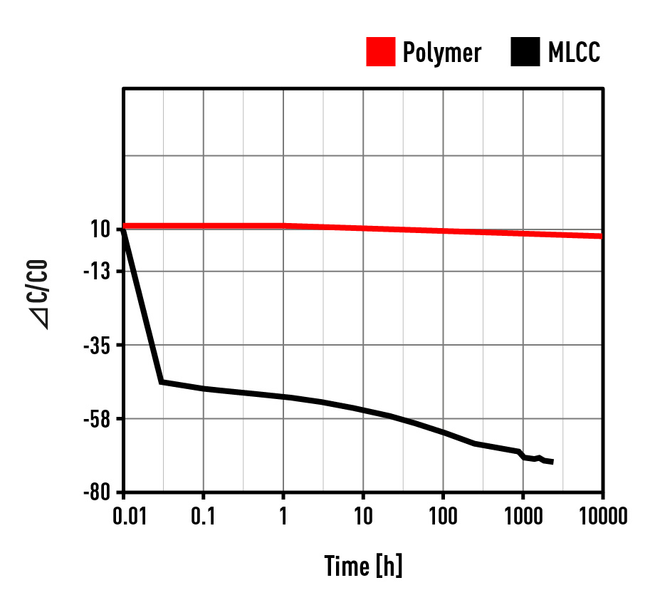 Figure 2: Comparison of typical temperature characteristics
Ceramic capacitors are brittle and sensitive to thermal shock, so precautions need to be taken to avoid cracking during mounting, especially for high-capacitance large sizes. The typical temperature range for ceramic capacitors is -40 to +85°C or +125°C, where their capacitance varies about from +5% to -40% having a sweet spot around +5 to 25°C. Polymer capacitors have great development potential to achieve higher ratings on density, field stress and temperature, yet are limited to +125°C due to their working mechanism and dielectric materials advancement; yet higher dielectric constant polymers enable a high energy density.
Piezoelectric effects
Most dielectrics of ceramic capacitors exhibit piezoelectric effects that can cause unexpected signals in certain circuits. In some cases, the piezoelectric effect may result in the appearance of electrical noise. When an electric potential, or field, is applied on the surface of an MLCC, it causes a deformation at a frequency range from 20Hz to 20kHz, that is audible to humans. This is the MLCC acoustic noise or singing noise. A MLCC alone is in most cases not sufficient to generate problematic or disruptive sound pressure l, but soldered on a PCB the MLCC generates a spring mass system, which increases or dampens the oscillation, depending on the frequencies.
 Figure 3: Temperature characteristics comparing capacitor types
MLCCs are exposed to more than 10 reliability test including thermal shock, board flex (bending), and biased humidity tests, depending on the target application. The board flex test evaluates the mechanical resistance to cracking when MLCCs are subjected to bending stress on the PCB that the MLCC is soldered on to. The bending of the PCB can occur frequently during manufacture and during operation under temperature variations. Flex cracking is due to excessive circuit board flexure. As for the causes of board flexure, there are various causes including problems during the manufacturing process, such as solder stress due to an inappropriate amount of solder, stress applied at the time of depaneling or screw fastening, or board flexure at the time of final assembly. Other causes are drops, vibration, or thermal expansion during use. Ceramics are strong in compression but weak in tension. Thus, when a soldered MLCC experiences excessive board flex, a crack is easily generated in the element. A flex crack can cause an electrical conduction between opposing internal electrodes. It is also possible that a fail open can progress to a fail short with continued product usage. If a crack on a capacitor element progresses to a short circuit failure, it may cause problems such as heat generation, smoking, or ignition.

Figure 4: The MLCC acoustic – or singing – noise
Most ceramic capacitors have a fairly high voltage rating. If the capacitor experiences a voltage between its terminals higher than its rated voltage, the dielectric may break down and electrons will flow between the thin metal layers inside of the capacitor, creating a short circuit.
Construction comparisons
Polymer capacitors are supplied as chip type or wound type products. Solid polymer capacitors are not regarded as components which are likely to be replaced in a device, they are often made in surface-mount technology, allowing them to take up less space on the PCB at the expense of being harder to unsolder if replacements are necessary.
The use of solid electrolyte is a major advantage over electrolytic capacitors. In a wet electrolytic capacitor overheating can cause the electrolyte to evaporate. As it evaporates, pressure builds up within the capacitor and it may burst or even explode. Solid polymer capacitors do not have such risks– the capacitor either shorts or starts acting like an open circuit.

Figure 5: The construction of Panasonic’s SP-Cap and the POS-Cap capacitors
Generally speaking, the reliability of polymer capacitors is much better than the reliability of MLCCs. If space is limited, however, all-purpose MLCCs are the best option. They are also suitable for applications where high withstand voltage performance and ability to withstand reverse voltage are required. Typical polymer capacitors are a good choice when both, higher capacitance and low ESR are important. Potential cost and space savings when comparing single polymer capacitors to an equivalent of multiple MLCCs can make a big difference in designing PCBs.