


The appeal of FPGAs is that it is possible to change their functionality after they have left the factory, allowing users to configure them to meet the exact needs of one or more applications. Their power needs however can be complex, requiring power solutions that have to provide up to 10 separate rails and even reconfigure voltages on-the-fly.
Challenges when powering FPGAs
It is essential that an FPGA is powered in line with the manufacturer’s data sheet to ensure correct operation and avoid damage. However, they require more than the single supply rail that satisfies many ICs. In general, FPGA power consumption has a static and dynamic element as well as specific power needs for certain sections such as the transceiver or I/O section.
The static part is mainly due to a combination of bias and leakage currents and the dynamic part depends heavily on circuit design or application, the clock frequency and the configuration of the I/O – especially the voltage selected.
Estimating the power budget for any FPGA-based design can be difficult, so most FPGA suppliers provide tools that allow designers to build a picture of the sometimes complex power needs for these designs. Considering this estimate, designers are generally well advised to allow a little extra capacity in their power budget. This will allow for any design changes to the FPGA configuration during the development phase and also provide for the start-up phase inrush current that is greater than when operating normally.
Designers also have to deal with the low voltages (typically sub-Volt) needed for the core logic that lead to high currents (many tens of Amperes) that create large losses and generate substantial heat in the system. There are also fairly onerous requirements in terms of sequencing the various power rails, as well as meeting minimum and maximum ramp-up times during power-up. FPGAs are also fairly intolerant of inaccurate voltages, meaning that the voltage tolerances on the supply are generally quite tight, which can drive cost and complexity in the power solution.
One of the great advantages of FPGAs is their flexibility. However, as far as power is concerned this tends to add to the headaches. Many FPGAs include configurable transceivers that require the I/O voltages to be reconfigured on-the-fly, meaning that the power system must be software configurable. While the currents here are, relatively speaking, quite low, there is an expectation that future FPGAs will have configurable core voltages to allow the energy consumption to be managed dynamically. This will require the main supply rail to also be configurable presenting a further challenge. This is often referred to as adaptive voltage scaling, or AVS.
Powering modern FPGAs
Initially, the challenges of powering FPGAs may seem to require an incredibly complex power system to meet all of the requirements, modern digitally controlled PoL converters possess many of the features required for a successful implementation.
In general, most FPGAs require that the internal core voltage is the first rail to rise, followed by the I/O voltage rail and the auxiliary rail. Using separate PoL modules for each rail allows sequencing time delays to be configured, easily achieving the requirements of the FPGA specification.
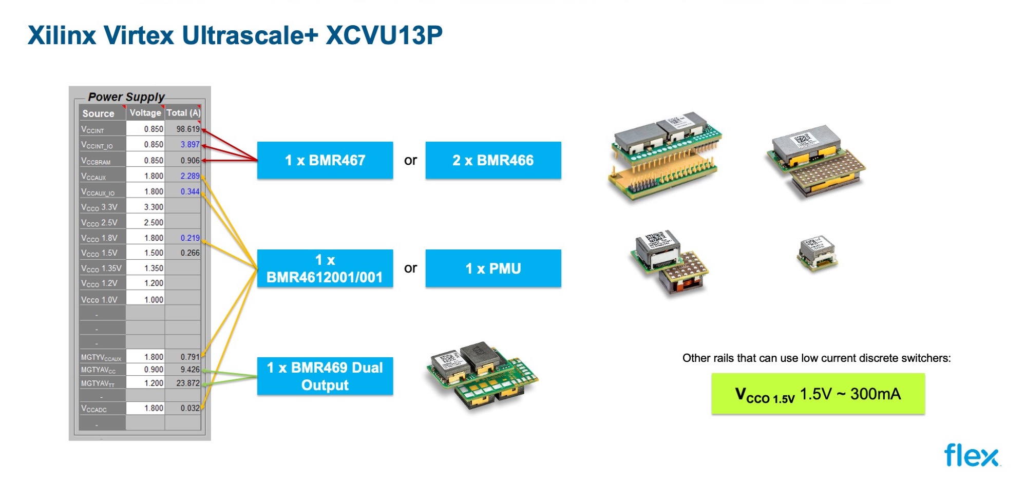
Figure 1: The power needs of Xilinx’s Virtex 16nm FPGA can be met with PoL modules
As an example, Figure 1 shows the complete power needs of Xilinx’s Virtex Ultrascale+ VCXU13P FPGA in a particular configuration. These power needs can be met with just three types of Flex PoL modules. The main core voltage of 0.85 V at approximately 100A can be supplied from a BMR467 PoL converter. This DC/DC converter is capable of supplying up to 120A of output current at voltages between 0.6 and 1.8V, configurable via the PMBus or pin-strap – easily meeting the FPGA requirements. The small footprint of 50.8 x 19.05 x 10.4mm enables the PoL to be placed close to the FPGA to minimise the length of high current traces. For space-constrained applications, a system in package (SIP) version reduces the footprint to 50.8 x 8.2mm. For extreme high power applications, up to four BMR467 PoLs can be used together to give a total power capability of 480A. The device has an MTBF of 10.49 million hours.
Another possible solution could be to use two 60A BMR466 devices connected in parallel. This also adds some flexibility in terms of component placement, yet still comfortably deals with the required current level.
The third option is the BMR461, a PoL converter that accepts voltages between 4.5 to 14V and delivers up to 18A over 0.6 to 1.8V, reducing slightly to 15A at an output of 3.3V. The small, surface mount PoL measures 12.2 x 12.2 x 8.0mm and offers an MTBF of 24 million hours.
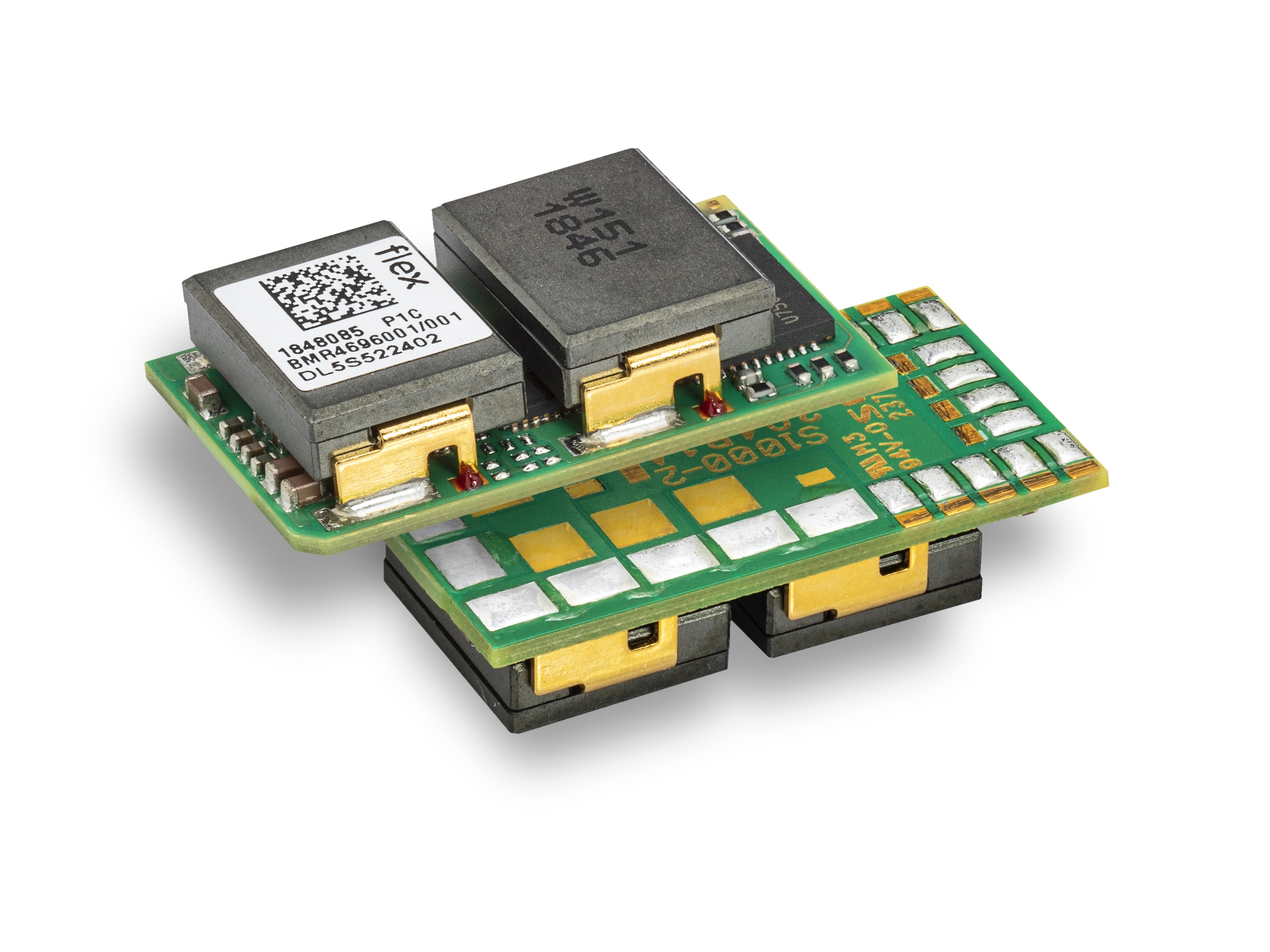
Figure 2: The BMR469 is a dual output (2x 25A) PoL module
The Flex Power Modules BMR4696001 can be configured for either single- or dual-output applications, which allows the single device to be used for two FPGA voltage rails, thereby saving cost and board area. This 2 x 25A device occupies just 25.4 x 14.5 x 5.8mm yet is capable of delivering 100W of power at efficiencies up to 94.3%. A four-module current sharing capability allows single-rail currents up to 200A to be generated.
The Flex Power Modules PoLs incorporate output voltage programming that support core and I/O voltages from 0.6 to 5.5V. The integral AVS allows designers to save energy with on-the-fly changes to the FPGA’s core voltage.
The intelligent PoLs are based upon a control loop with fast transient response, making them suitable for dealing with the load fluctuations that occur in FPGA applications. Furthermore, the control loop parameters can be configured digitally and dynamic compensation is sometimes offered. A number of in-built features simplify the task of designing for FPGA applications including the ability to synchronise and spread phases, margin up and down and track output voltage using its differential sense pins.
Protection features built-in to all Flex PoLs include a shutdown for input under- and over-voltage, over-temperature protection and output over-current and over-voltage protection for safe operation and shutdown of the PoL during fault conditions. The devices also have full PMBus compatibility including the ability to monitor and report current, voltage and temperature.
To get the most from Flex Power Modules’ PoL modules (and the FPGA design), the Flex Power Designer software is available free of charge to designers. The software allows all parameters within the PoLs to be configured, including sequencing, ramp times, phase spreading and AVS. The software package also has the ability to monitor power modules and create graphs of key parameters, such as temperature against time.
A recent major upgrade of the software added thermal simulation capabilities, which is believed to be a unique feature in this type of software. It contributes to removing risks in power system design, reducing design costs and shortening time to market.
Designing power solutions for the latest FPGAs with their complex multi-rail requirements and timing needs as well as high power levels may seem daunting at first but modern, digitally controlled power modules, have many in-built features that suit this application very well. Combining this with software and tools, such as evaluation boards, enables designers to simulate and prototype designs, removing much of the risk, and getting them to market faster.