


Common power conversion applications include AC/DC and DC/DC converters seen in many commercial and industrial products and AC/AC or DC/AC inverters found in motor drives, UPS units and more. Conversion topologies use switched mode techniques for highest efficiency and smallest size and cost. Inevitably, switching noise is produced and output filters are required to minimise EMI and provide reliable operation of the power converter and load.
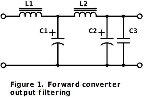
Filtering for DC outputs is well understood and usually comprises simple LC networks to provide energy storage where necessary and reduce differential noise down to acceptable levels. Figure 1 shows a typical output stage for a forward or ‘buck’ converter used at high power. L1 is sized in inductance to give a fixed ripple current for fixed frequency giving a ripple voltage across the ESR of C1. L1 has to pass the peak output current without saturation. This means it is often quite a large component comprising a powdered iron or gapped ferrite core. However, noise spikes may pass through with little attenuation due to the inductor’s high self-capacitance. L2 and C2/C3 form a low pass filter to attenuate noise. L2 can be quite small in value but must still pass the full output current without saturation. In fact, L2 should not be oversized in inductance as operating load current-steps through it produce unwanted voltage steps according to E = -Ldi/dt. C3 is sometimes added, as a parallel combination of an aluminium electrolytic and film capacitor provides low impedance across a wider range of frequencies. Sometimes filtering is also added to reduce common mode noise between output and local ground. At lower power, when a flyback or buck converter is used, energy is stored in an inductive component equivalent to L1 further back up the power train. L2 and C2/C3 may still be included though to reduce noise.
Suitable components for the inductor and capacitors can be found in the TDK EPCOS range. For example, L1 and L2 can be formed from windings on its extensive range of gapped ferrite E-cores. C1 and C2 could be from its B41890 series of long life, low ESR aluminium electrolytics.
AC output Inverters, sometimes with variable frequency, have similar considerations for noise filtering but complicated by the fact that the filter is also passing low frequency high current AC. Motor drives are a good example where the inverter typically produces three-phase AC outputs with variable frequency and amplitude for fine speed and torque control. The outputs are generated from a three-phase bridge of IGBTs or MOSFETs under high frequency PWM control, the pulse width being modulated at the low AC frequency required by the motor. Without filtering, the connections to the motor, which may be some distance away, would comprise high voltage, high frequency square waves with fast rise times and variable pulse width. The motor winding inductance acts as a filter for the high frequencies, effectively leaving only the average, low frequency AC. Although this basic scheme works has some major drawbacks:
- Along extended cable lengths to the motor, differential and common mode noise from the switching waveforms produces EMI usually way over acceptable limits as set by international standards such as EN 55011, Class A/Group 1 or EN 61800-3 Category C2. Shielding the motor cables helps but is expensive and may not limit common mode emissions.
- Fast edges of the waveform produce ringing with the inductance and self-capacitance of the cable producing voltages, which can break down the motor winding insulation.
- The common-mode element of the switching waveform can find a path to ground through the bearings of the motor, causing damage and premature failure. The mechanism is metal transfer from the bearing balls and races called ‘electrical discharge machining’ or EDM. This causes erosion and bearing failure in as little as four weeks after installation with peak bearing currents of up to 20 amps being reported.
- Audible noise can also be an issue, if the PWM switching frequency is in the audible range, below about 20kHz, and the inverter output is not filtered, stator lamination vibration can cause an annoying ‘whine’.
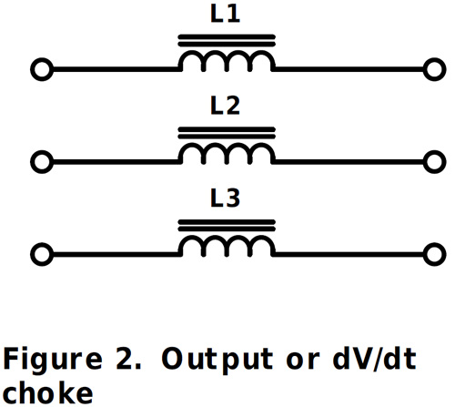
Filters on the output of the inverter are the solution to these problems with several types available depending on the severity of the effects. Simple in-line chokes as shown in Figure 2 reduce the differential noise by increasing the rise time of voltage pulses which limits stress on the motor insulation and reduces motor noise but without reducing common mode electrical noise. Shielded cables to the motor are typically still required to meet EMC standards. Common-mode leakage currents through motor bearings are also not reduced. This simple solution can be effective though, with cable lengths up to about 50m if bearing currents are minimised by careful earthing arrangements. The filter does have to pass the full motor drive current without saturation or overheating. Parts in the B86301U*R000/S000 range from TDK EPCOS would be suitable examples with current ratings up to 1500 amps.
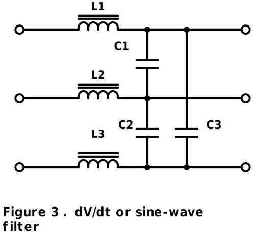
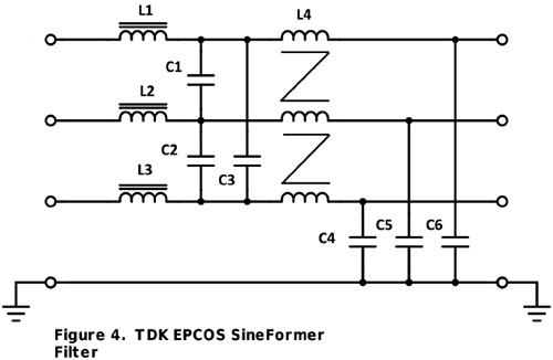
A complete solution is a filter such as the SineFormer type from TDK EPCOS, in its B84143V*R127 range, with rated current and voltage up to 320A and 520VAC (shown in Figure 4). Here, an extra common mode choke L4 and ‘Y’ capacitors C4, C5 and C6 are employed to dramatically reduce common mode currents. L1, L2 and L3 along with C1, C2 and C3 reduce differential noise. The result is a reduction of dV/dt on waveforms to less than 500V/µs, lower motor noise, significant reduction in bearing currents and lowest EMI. Benefits are that unshielded cables can be used up to perhaps 1000m, the motor’s life is extended and there is even the possibility of using a smaller motor for a given application. The filter is maintenance-free and can be easily retrofitted to existing applications.
Although the SineFormer may seem like an expensive solution, it can remove the need for costly shielded cabling with its associated complex termination. Calculations by TDK have shown that for motor cables lengths of greater than 50m, the combination of unshielded cable and SineFormer can be overall lower system cost. If the cost of early failure, downtime and replacement of a motor is factored in, the SineFormer wins every time. Figure 5 summarises the performance of the filters discussed.
| Filter type | Line to line voltage | Line to ground voltage | Radiated interference | Motor bearing current reduction |
| dV/dt filter | Almost no improvement | None | ||
| Sine-wave filter | Little improvement | Low | ||
| SineFormer™ | Almost eliminated | Optimal |
Figure 5: Summary of TDK EPCOS filter properties
Click here for more information.