


The industrial sensor market is huge and amongst the sensor categories, temperature, pressure and level sensors dominate. The level-sensing market was estimated at over $4 billion in 2018 with almost 248 million units shipped, according to a report from Research and Markets. Level sensing determines the liquid/material level in a system/container. The measurement can be continuous or set to trip after a certain level has been reached. Continuous monitoring is particularly suitable for use in process control, inventory management and for predicting downtimes and continuous level sensors are projected to witness high demand in the coming years.
There is also increasing adoption of non-contact level sensors in various end-use applications, such as waste water processing, mining, and power stations. The common technology for non-contact level sensing is ultrasonic. According to Persistence Market Research, the ultrasonic level sensor market was valued at just under $140 million in 2016 and is expected to reach approximately $298 million by the end of 2025. The analysts cite the strong demand from waste water management, oil, and gas companies as a key driver of growth.
Another use for non-contact ultrasonic sensing is in the measurement of flow of various liquids and gases. Ultrasonic flow sensing is driven by the oil and gas industry, primarily in North America, but also in developing markets like China and India. Increasing regulations to control emissions of toxic gases – from power plants and oil rigs – also help spur the growth of ultrasonic flow sensors. Based on their application demands, ultrasonic sensors must continue to get smaller and more rugged. What this directly impacts is the power subsystem design of these sensing systems.
Ultrasonic principles
Ultrasonic sensors emit high-pitched sound waves with frequencies higher than the audible limit of human hearing – over 20kHz. Most of these sensors will use frequencies in the range of 30kHz to a few MHz. These systems can have a single transducer or two transducers. Level sensing can be done using a single transducer, while flow sensing, which uses the time of flight of an ultrasonic wave and its variation depending on the flow rate of the medium, typically uses two transducers.
For a level-sensing or a distance measurement application, the principle is simple. The transducer emits an ultrasonic signal and measures the time it takes for the signal to get reflected from the surface of the liquid. The time of flight (ToF) of the ultrasonic signal can be calibrated to read the tank level, the distance of a critical machinery, or even the fluid makeup/concentration (see Figure 1).
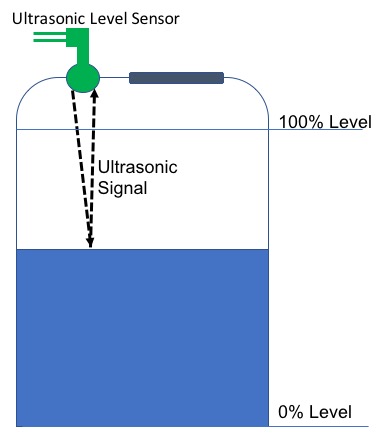 Figure 1: Conceptual drawing of an ultrasonic level sensor
For measuring the flow rate, two transducers are located at two points – one to measure the downstream ToF and the other to measure the upstream ToF (See Figure 2).
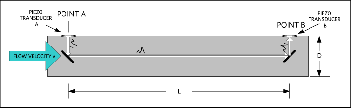
Figure 2: Typical ultrasonic ToF water-flow meter
This is a reflective flow meter, which requires the reflector surface to be built in within the meter that is attached to the pipe. The arrangement of the reflector surfaces within the flow meter is unique to every meter manufacturer. Consequently, the ultrasonic ToF principle is based upon the ToF of an acoustic signal in the water. The upstream ToF is longer than the downstream ToF, since the water velocity aids the acoustic signal in the downstream direction and impedes the acoustic signal in the upstream direction. This difference in ToF determines the velocity of the flowing water.
This is just one way of measuring the flow. One can also use a diagonal arrangement or a non-invasive arrangement (Figure 3).
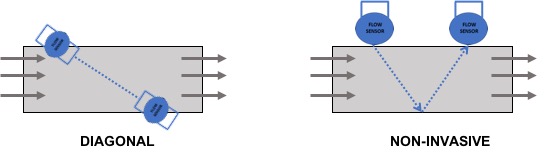 Figure 3. Measuring flow with an ultrasonic level sensor
The choice of ultrasonic sensors used depends on the type of medium that needs flow-rate measurement. To measure the flow of gases, lower frequency ultrasonic transducers are needed. To measure liquid flow, higher frequencies (above 1MHz) are required. The flow tube that houses the transducers and the reflectors needs careful mechanical construction. In ultrasonic ToF measurement there is no moving parts and accuracy is diminished by less than 1% over the operating life.
Building a sensor system
Ultrasonic sensors involve an analogue front-end that would incorporate transmission, receiving, and control circuits, along with a microcontroller/microprocessor for the calculations. In some cases, a separate time-to-digital converter chip may be used as well. These sensors are also getting smaller in size to be able to fit in existing assembly lines and in narrow openings.
Chirp Microsystems claims to provide the world’s smallest ultrasonic ToF sensors (Figure 4). The Chirp CH-101 and CH-201 are the first commercially available microelectromechanical systems (MEMS)-based ultrasonic ToF sensors. At 3.5 x 3.5mm, they combine a MEMS ultrasonic transducer with a custom, low-power CMOS SoC that handles all ultrasonic signal-processing functions.

Figure 4: Chirp Microsystems’s tiny ultrasonic ToF sensor
As complex industrial systems shrink in size, they’ll need regulated power solutions that are tiny, rugged and which display the lowest heat dissipation to be able to be implemented in small, fanless ultrasonic sensors that operate 24/7 in an industrial environment. Generally, these systems will be powered by a DC voltage in the 10 to 30V range, supplying less than a few hundred mA of total system load current. The system will need to be protected from reverse polarity connection as well from over-voltages (up to 42 or 60V) due to ringing.
The system operating temperature conditions are generally up to 60 to 70°C, and so the ICs housed within the sensors system must be rated at up to 125°C. The switching power losses must be kept to a minimum since this is directly correlated to the heat dissipated by the system. Depending upon the use-case, there may be stringent EMI testing on the system, so it is important that the switching regulators are CISPR EMI tested and do not add to the EMI noise in the system.
Power problems
Consider a miniature ultrasonic distance measurement sensor which operates from a 15 to 30V power supply. The device must withstand input voltage ringing up to 60V, provide various load voltages and consume up to 50mA total current. Three typical load voltages are 5V at 5mA, 3.3V at 35mA and 2.5V at 10mA to power the microprocessor, ultrasonic burst generator, echo receiving path (local interconnect network, or LIN), sigma-delta ADC, SAR ADC, bandgap voltage reference and time-to-digital converter.
Using a low drop-out regulator (LDO) to create these load voltages is not efficient and will generate lots of heat. In this example, the power losses in the LDOs are as follows:
PLDO = (VINmax – VLOAD) x ILOAD; where VINmax is the maximum input voltage (30V in this case); power dissipation for the 5V LDO is (30V-5V) x 5mA = 125mW; power dissipation for the 3.3V LDO is (30V-3.3V) x 35mA = 935mW; power dissipation for the 2.5V LDO is (30V-2.5V) x 10mA = 275mW; load power = (5V x 5mA) + (3.3V x 35mA) + (2.5V x 10mA) = 166mW
Total power dissipation is 1,501mW, which is a large heat source for the sensor. Note that the actual load power, which is the useful power to run the sensor’s circuitry, is only 166mW while 1,335mW is wasted power due to the LDO’s inefficiency.
Switching DC/DC regulators are more efficient and can reduce total power dissipation significantly. In this example, a DC/DC regulator with 85% efficiency only dissipates (1/85%-1) x 166mW = 29.3mW. This results in a total power dissipation of only 195mW, an 87% reduction compared to the LDO solution.
Another design challenge for ultrasonic sensor is size. Clearly, the DC/DC solution offers a much lower power dissipation figure compared to the LDO solution. The next problem is to fit this power solution into a small area. In this example, the cubical distance sensor’s overall outer dimensions are 24.5 x 55mm. Allocating the space for the LED, connector, and other mechanicals, leaves roughly 600mm2 (15 x 40mm) of board area for all electronics.
A typical DC/DC converter which uses an external output filter inductor would take approximately 10 x 15mm (150mm2) per rail. A three-rail design would occupy 450mm2, or 75% of the available board area. This option takes up too much precious board space, leaving little room for other electronics or innovation.
A more effective solution is an integrated power module, such as the Himalaya uSLIC MAXM17552. By integrating the output filler inductor and most external components, this solution fits in a 6.0 x 10mm (60mm2) area per rail. With three rails, this would cover 180mm2, roughly 30% of the board area. The power module operates from a wide input voltage range of 4.5 to 60V and provides 100mA of output current. Its output voltage is programmable from 0.9 to 5.5V.
Figure 5 shows the size of the MAXM17552 evaluation kit. When compared to a traditional DC/DC converter with external output filter inductor, it is 2.5x smaller.
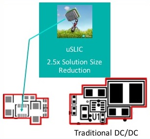 Figure 5: The MAXM17552 uSLIC compared with a traditional DC/DC converter
The incorporation of discrete components, such as inductors, in the same package reduces the form factor of a highly efficient, regulated power subsystem. Designers need to use the smallest power subsystems that operates in harsh industrial conditions that features low heat dissipation to build the small, ruggedised ultrasonic sensor required today.