


Answer: Yes, most battery-powered systems need to implement a battery charging concept. In this article, Frederik Dostal, Field Applications Engineer, Analog Devices describes how different power management functions are designed and optimised for battery-operated systems.
An example system diagram that contains many of the functions that are needed in battery-powered electronics is introduced. Different aspects of power conversion efficiency are also discussed.
Introduction
Many systems require battery power. Batteries are used for power redundancy in case of a line power outage, but mostly in portable equipment, which can be large like an electric vehicle or small like a hearing aid. In all battery-powered systems, power efficiency is key. The less efficient the power supply, the larger and more costly the battery for the same runtime. Also, batteries supply different voltages depending on the charge state. This requires special power converter capability to regulate the varying voltage from the batteries to a stable voltage for the system electronics. Most battery-powered systems today implement a rechargeable battery rather than a primary non-rechargeable battery. This requires systems to include a battery charger. This article explains various battery charging architectures along with new, innovative examples. Certainly, power conversion efficiency is a must.
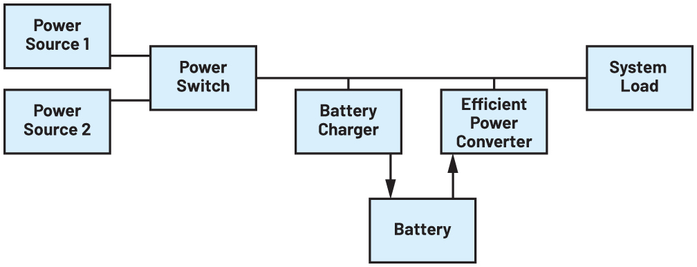
Figure 1. A simplified system diagram of a battery-operated system.
Figure 1 shows a system diagram of a battery-operated system. While the exact implementation varies for different use cases, the main function blocks shown in this diagram are usually available in all systems. There is some supply voltage, which sources the power to the system. This connection often needs to be switchable. If the power source is a wall wart AC line power converter, unplugging the low voltage power cable is the same action as switching the power switch in Figure 1 to the off position. Such power path management is necessary to avoid losing valuable battery energy to additional circuitry attached to the source. Also in Figure 1, we see a potential second power source. The power switch block would switch the power flow coming from Power Source 1 or Power Source 2. For example, Power Source 2 may be a USB 5 V power source.
Then the power is converted to safely charge the available battery and/or to power the system directly. If no input power is available, the stored energy in the battery is taken with a very high efficiency switch-mode power converter to power the system.
Power efficiency in battery-powered systems
The charging of a battery usually does not have to be very power efficient. In most battery-powered systems, except for energy harvesting, there is enough power available to recharge a battery. For example, when a mobile phone is connected to a phone charger, the exact efficiency of the charging process is typically not relevant to most people.
In energy harvesting systems, however, the power efficiency during the charging process is key. Ultimately, higher power efficiency during charging directly translates to smaller energy harvesters, which reduce system cost and may decrease system size.
All battery-powered systems, however, value power conversion efficiency while the battery is discharged. Higher power conversion efficiency during this process directly translates to smaller battery capacity for the same system operating time.
The efficiency of such a power conversion stage from the battery to generate the voltage required for the load needs to be evaluated further. There is a full load conversion efficiency, which provides information about how long a system may run at nominal load, and there is also the light load efficiency, which matters in many systems. This is the efficiency of power conversion during very light load conditions. For example, when we look at a battery-powered smoke detector, it runs at a low load current smoke detecting stage for up to many years until the moment when smoke is detected and an alarm sounds. The alarm is enabled by a high current, but the power efficiency during this phase is not so relevant for the point in time when batteries need to be replaced.
For a very low power load efficiency, the quiescent current IQ is relevant. The lower, the better. This quiescent current together with the switching scheme determines the low load efficiency. In Figure 2, there is a typical efficiency plot shown with and without light load efficiency mode. Light load efficiency mode is the blue curve and fixed switching frequency mode is the black dashed curve. Many power conversion circuits have such a mode to increase the light load efficiency. Typically, the way it works is that the constant switching frequency is stopped, and a few switching pulses are generated only when the output voltage dips slightly. In between those bursts, the power converter shuts down many functions to save power. These low power modes may differ slightly in regard to the exact architecture from IC to IC, but the result of such special modes is always a very high efficiency at light loads.
The efficiency difference at 1 mA output load is quite high in Figure 2. With power save mode activated at a light load of 1 mA (even down to 100 μA load), we see 50% power conversion efficiency. At 600kHz fixed switching frequency, without power save mode activated, we only get roughly 15% efficiency.
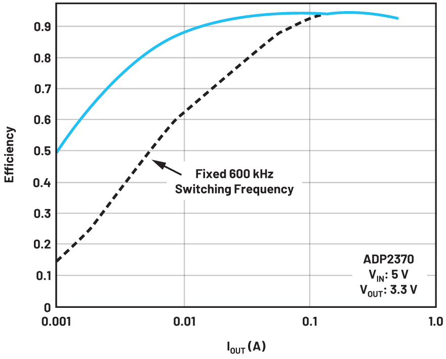
Figure 2. The power conversion efficiency of an ADP2370 buck regulator with low load power saving mode activated and with fixed 600kHz switching frequency at all loads.
Power conversion challenges
As mentioned, power conversion efficiency is very important in battery-powered systems. All existing types of topologies may be chosen for a battery-powered system. However, one topology that is used often is the four-switch buck-boost converter. Many systems require 3.3V of supply voltage and are powered by a single lithium-ion battery cell. Such cells provide a nominal voltage of 3.6V, but toward their discharged state, they only provide between 2.8 and 3.0V. For the longest run time of the system, we need to utilise as much energy from the battery as possible. In 3.3V systems, this forces us to step down from 3.6 to 3.3V when the lithium-ion battery is fully charged. However, when the battery is toward the end of its discharge, 2.8V need to be boosted to 3.3V. This requirement calls for a buck-boost circuit. Many different types of buck-boost circuits exist. Just to name a few, suitable topologies include the transformer-based flyback, two-inductor single-ended primary-inductor converters (SEPICs), and the four-switch buck-boost. The four-switch buck-boost is usually chosen since it typically offers the highest power conversion efficiency compared to the other two topologies.
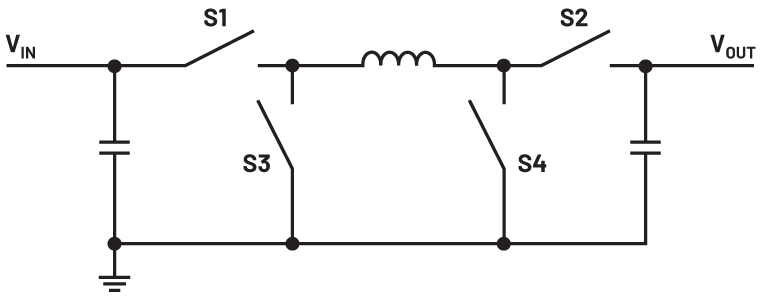 Figure 3. An example of a four-switch buck-boost power converter such as an LT3154 buck-boost DC-to-DC converter.
It is possible to avoid a buck-boost topology altogether by using two lithium-ion batteries in series, rather than just one. Then only a simple step-down stage power converter is needed. However, this requires additional effort and cost for the second battery cell. Also, the charging of two battery cells is a bit more challenging than just charging a single cell. When two cells are used in series, the max voltage of the two cells in series is 7.2V. This requires a power converter with a higher voltage semiconductor process than the typical 5.5 V max processes derivates. This is not a problem but may make the semiconductor of the DC-to-DC power converter slightly higher cost.
Selecting the right battery charger
There are many battery charger ICs available on the market. A battery charger is a device that provides voltage and current in a manner that safely recharges batteries. When choosing an integrated circuit, the first decision that needs to be made is whether to use a linear charger or a switching charger. Linear chargers are like linear regulators. They can only step down an available voltage. The input current roughly equals the output current.
For example, if a depleted battery has a voltage of 0.8V, and the available system voltage is 3.3V, the linear charger must step down to 2.5V. If the charge current is 1A, 2.5W is dissipated into heat by the linear charger. While this may be possible, imagine a system voltage of 12V. Here the dissipated power amounts to 11.2W. Linear chargers are a reasonable choice for applications with low charging currents and a system voltage close to the battery voltage.
For all other applications, switching chargers are recommended. Most battery charger ICs available are switch-mode battery chargers. They are classic switch-mode power supply (SMPS) devices with special features enabling battery charging. They can charge with constant voltage or constant current, sometimes even both, and they provide special features to make charging safe. This can be a timer to detect if an attached battery is defective or it may include a temperature sensor to limit battery temperature during charging to avoid thermal runaway in different circumstances. A feature that is becoming more and more popular is the safety check between a battery pack and a battery charger, which monitors whether an authorized battery is attached to the system.
Figure 4 shows a standalone SMPS battery charger solution. It is the MAX77985 and it implements the step-down SMPS battery charger as well as a power path switch. The power path switch is essential to most applications. It can disconnect the input voltage rail from the battery, once the battery is fully charged, to prevent the battery power from dissipating through any circuitry that might be attached to the input power line. Also, the solution has a digital I2C interface to change certain settings to the charger IC as well as for telemetry purposes. To make a battery charger as flexible as possible, digital interfaces enable settings for different battery types and battery sizes.
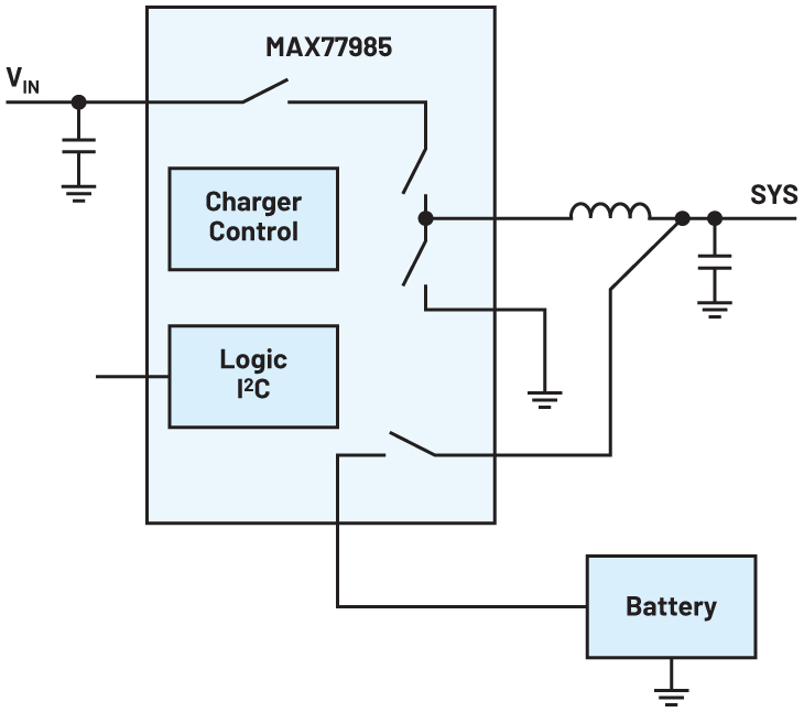
Figure 4. A MAX77985 standalone battery charger simplified circuit diagram.
Among many different features, one item is especially noteworthy. The integrated power switches in the MAX77985 can not only be used in step-down mode for charging the battery but the switches can also be used to boost the battery voltage to a higher system voltage. In a way, this specific battery charger combines the system power converter with a pure battery charger.
Battery-powered equipment requires many different electrical functions. Some products offer only basic functionality, while other products are highly integrated with most functions available in an integrated circuit. Such products are called system power management integrated circuits (PMICs) and are especially popular in battery-powered applications. This has multiple reasons. One is that many battery-operated systems are rather small and as such require a compact system solution. The second reason is that each separate IC has some quiescent current; some power that is always consumed when the IC is turned on or off. This will eventually drain the battery. Combining many different integrated circuits into one PMIC device reduces the system’s quiescent current in most cases.
The availability of high capacity lithium-ion batteries has especially transformed the landscape for battery-powered systems within the past 20 years. Many integrated circuits are available for charging and discharging those batteries efficiently. Today a lot of research is being performed for future battery construction to increase the capacitance per weight and volume and to increase the possible charging speed while maintaining the safety of operation. There is no end in sight to innovations in battery charging and discharging integrated circuits to keep up with these battery developments.