


This article originally appeared in the Dec’23 magazine issue of Electronic Specifier Design – see ES’s Magazine Archives for more featured publications.
By Rolf Horn, Applications Engineer, DigiKey
M2M is not new, having been a part of the digitalisation of the factory stretching back decades. This long history means there are many legacy networks in place presenting factory managers with a dilemma. Retaining older communication systems means missing out on the productivity benefits brought by Industry 4.0, but upgrading the factory to bring in Industrial Ethernet is expensive and disruptive. Worse, many older machines are typically controlled by a generation of programmable logic controllers (PLCs) that are not compatible with newer Industrial Ethernet protocols. Yet those machines could have many years of useful life left. An industrial gateway can provide a cost-effective interim solution by bridging between legacy infrastructure and an Ethernet backbone as it is phased in.
A short history of industrial automation
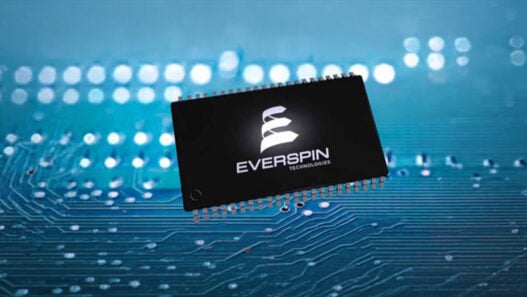
The digitalisation of factories really got started with the invention of the PLC, a specialised type of computer that continuously runs a single program, in 1969. A key advantage of a PLC is its virtually real-time and highly repeatable program execution. A good example is the Siemens SIPLUS unit which features an RS-485 serial interface (Figure 1).
In the early days of factory automation, manufacturers linked their PLCs to a central supervisory system using RS-232 serial data link with a maximum throughput of a few hundred kilobits per second (Kbits/s). Later, RS-422 and RS-485 took wired communications to a more advanced level using differential signalling over a twisted pair cable. These systems allowed one controller to supervise up to 32 PLCs and offered a data rate of up to 10 megabits per second (Mbits/s) over a distance of up to 1,200 metres (m).
It is important to note that RS-232 and RS-485 are standards that specify the physical layer (PHY), not the communication protocol. In the industrial automation sector, several protocols have been developed to run on the RS-232 or RS-485 PHY. The protocols have been developed and supported by many PLC makers.
Ethernet enters the factory
However, since the turn of the century, Ethernet has provided the most accessible and proven solution for a modern factory network. Ethernet typically uses TCP/IP for routing and transport, ensuring Cloud interoperability, a capability that is well beyond RS-232 and RS-485 technology.
‘Industrial Ethernet’ describes Ethernet systems adapted for factory use. Such systems are characterised by rugged hardware and industrial standard software. Industrial Ethernet is a proven and mature technology for factory automation that allows a remote supervisor to easily access drives, PLCs, and I/O devices on the manufacturing floor. The infrastructure typically uses line or ring topologies because these help to shorten cable runs, reduce latency, and build in a degree of redundancy.
Standard Ethernet’s communication mechanism is prone to disruption and lost packets, increasing latency and making it unsuitable for the near real-time demands of fast-moving, synchronised production lines. Such an environment requires a deterministic protocol to ensure machine instructions arrive on time, every time, no matter how high the network load.
To overcome this challenge, Industrial Ethernet hardware is complemented by customised software. There are several proven Industrial Ethernet protocols available, including Ethernet/IP, ModbusTCP, and PROFINET. Each is designed to ensure a high level of determinism for industrial automation applications.
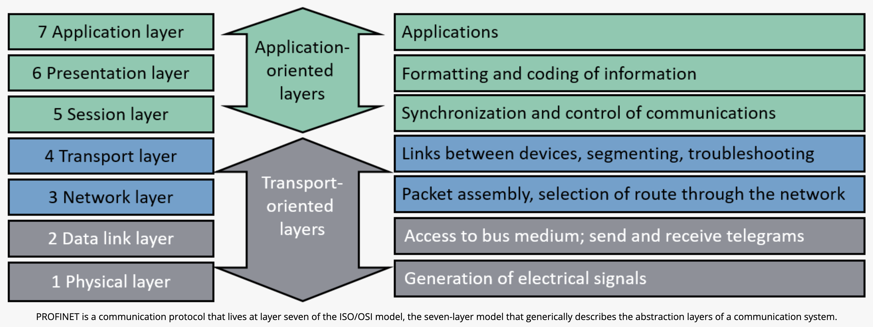
Standard Ethernet comprises the PHY, data link, network, and transport layers (which use either TCP/IP or UDP/IP), and can be viewed as a communication mechanism that brings efficiency, speed, and versatility. In contrast, Industrial Ethernet protocols use the application layer of the Industrial Ethernet stack (Figure 2).
A gateway to Industry 4.0
Updating legacy RS-232 and RS-485 factory automation systems to Industrial Ethernet is daunting for designers. There could be thousands of PLCs in a large factory and tens of kilometers of wiring. The cost and disruption caused by ripping out old systems for new replacements is not viable for many companies.
One strategy to limit cost and disruption is to commit to an Industrial Ethernet backbone while retaining legacy serial buses, PLCs, and machines. Then, when machines are replaced or when new machines are added to the factory, they can be specified such that they’re interoperable with the Ethernet backbone. This allows the factory to be gradually updated to the latest communications standards without production interruptions or major cashflow issues.
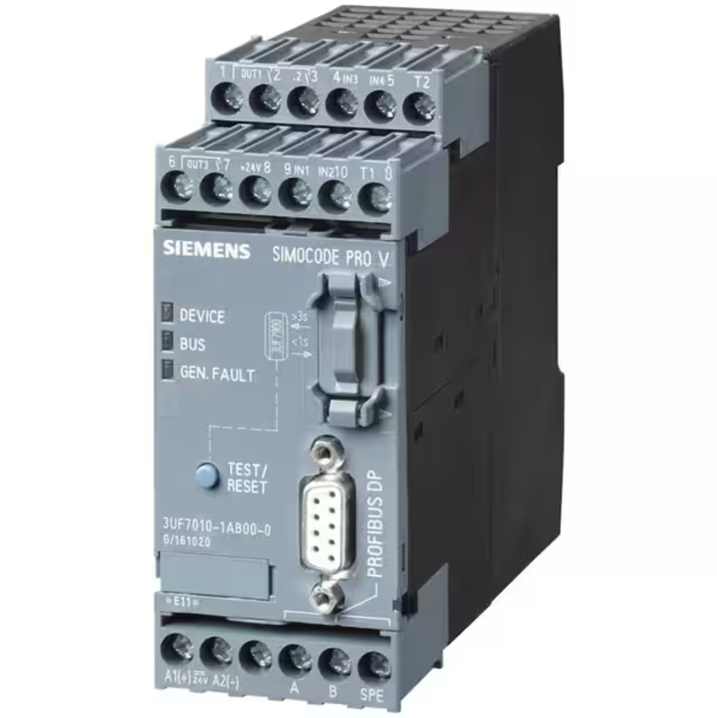
However, such a strategy creates a discontinuity between the RS-232/RS-485 and Industrial Ethernet networks. This discontinuity can be bridged with an Industrial Gateway Communication Device such as the 7940124932 or the 7940124933 (Figure 3) from Weidmüller.
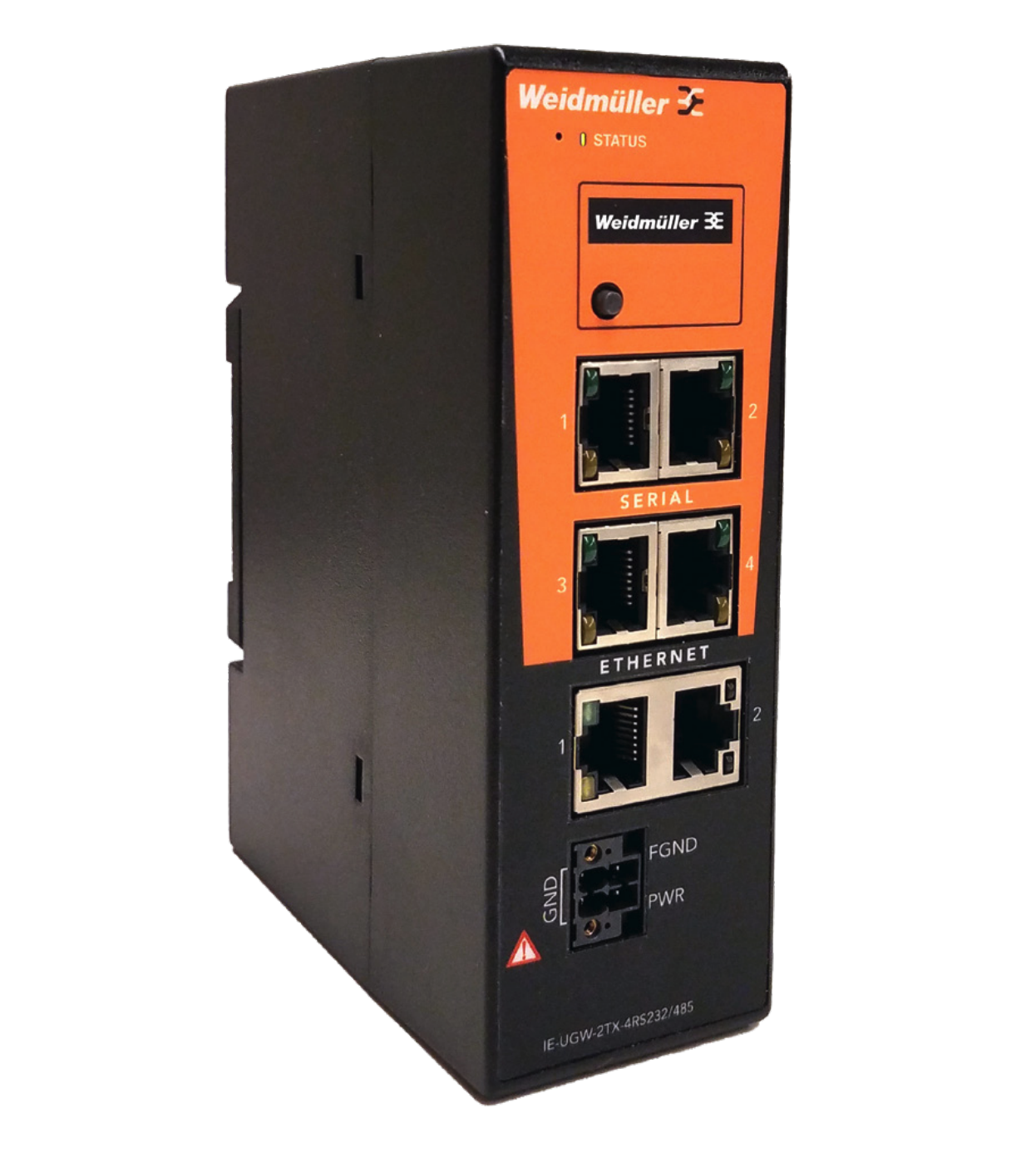
Each gateway is a single solution providing a cost-effective way to move data between PLCs and peripheral devices, using different protocols and without having to add wiring or multiple gateways.
These Weidmüller gateways offer two Ethernet ports and either two (in the 7940124932 model) or four serial ports (7940124933). They support EtherNet/IP, EtherNet/IP-PCCC, ModbusTCP, and S7comm (a Siemens Industrial Ethernet protocol) at up to 10 Mbits/s. On the serial side, the gateways can handle Modbus RTU, Modbus ASCII, DF1-CIP, DF1-PCCC, PPI, DirectNET, CCM, and HostLink serial protocols. Note that while the serial support is for RS-232/RS-485 standards, the serial input to the gateway is via the Ethernet-style 8-pin RJ45 connector rather than the RS-232/RS-485 type. The gateways are interoperable with PLCs from Automation Direct, GE, Rockwell Automation, Schneider, and Siemens.
Once configured via a browser, the Weidmüller gateways require no other equipment to transfer serial data formatted for one of the supported RS-232/RS-485 serial protocols into one of the supported Industrial Ethernet protocols, or vice versa. Data can be transferred to and from any port in any combination without the need to edit any PLC code.
Getting started with industrial gateways
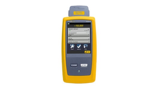
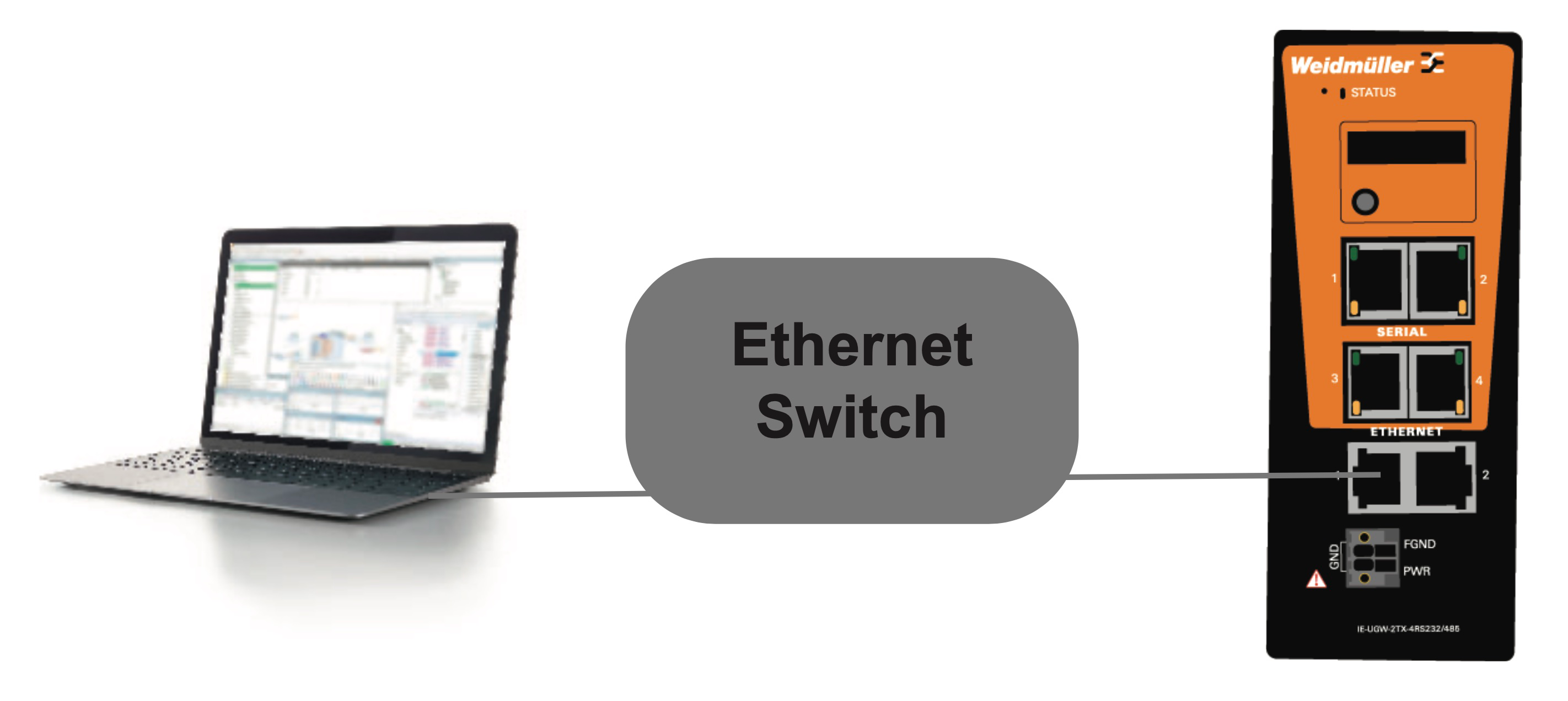
Configuring the Weidmüller gateway simply requires connecting the device to an Ethernet switch and then plugging in a PC into the other side of the switch (Figure 4). Once that’s done, the gateway can be connected to the 12 to 24 volt supply. The PC can then be used to log in through a browser window where the main gateway dialog appears. Dialogs then simplify the setup of the Industrial Ethernet network, as well as the addition of Ethernet and serial network devices to the gateway. Finally, the gateway serial ports are set to match the serial port configuration of the connected controller.
The key to the gateway’s ability to communicate between devices that use different protocols is the use of ‘tag’ data. The gateway enables the movement of tag data between different connected devices.
Tags are key when programming modern PLCs. They are names assigned to variables of any type stored in the PLC memory. The tags are stored in the PLC’s memory in a tag database.
In this tag database, all function blocks and program variables, as well as all other objects, are stored as tagged variables with attributes such as initial value, float, string, integer, Boolean, ASCII text, discrete inputs, and discrete outputs. The tag approach allows for a more efficient approach to more complex programming, but does require that the developer assigns the variable tags as well as the data type in advance of their use in the program. Data arrays can also be defined in the tag database.
For each PLC connected to the gateway, the developer must specify the tags from which data will be read and the tags to which that data will then be written. This first requires the tags from each PLC connected to the gateway to be programmed into the gateway before it can use them for communication across the network.
This is done from the PC connected to the gateway via the Ethernet switch. By selecting the ‘Add Tag’ icon in the configuration browser window, a dialog is activated that allows the developer to specify the tag name, data type, address, and other related information if required. It is also possible to speed things up by importing tags from a .csv file (Figure 5).
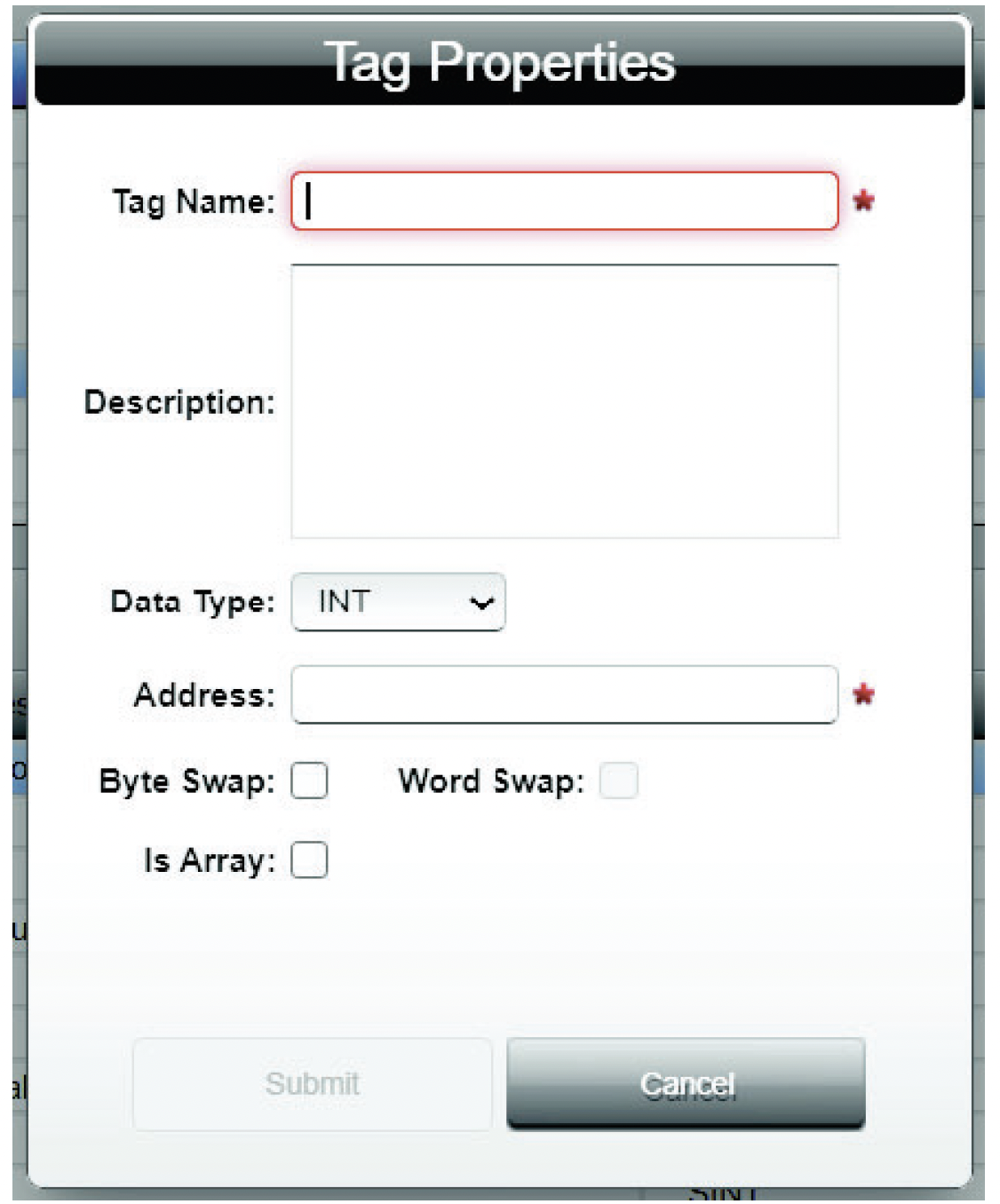
have been entered, the next step is to create a ‘tag map’. The tag map enables the gateway to read the data in the registers of a source PLC and write them to the correct destination device. The data in the registers is effectively the communication payload. The payload is extracted from the source tag using the source Figure 5. Dialog for programming the Weid müller gateway with PLC tag properties. (Image source: Weidmüller) PLC protocol, and then delivered to the gateway memory for transmission to the destination tag using the destination device protocol. It’s not critical that the source and destination tags have the same data type.
Creating the tag map is again performed from the PC connected to the Ethernet switch via the ‘Add Tag Map’ icon, which initiates the Tag Map Editor dialog (Figure 6). Each PLC connected to the network will need its own tag map. In the dialog, the target device is selected, and each tag to be used as a data source is ‘mapped’ to a data destination. The process is then repeated for all connected devices.
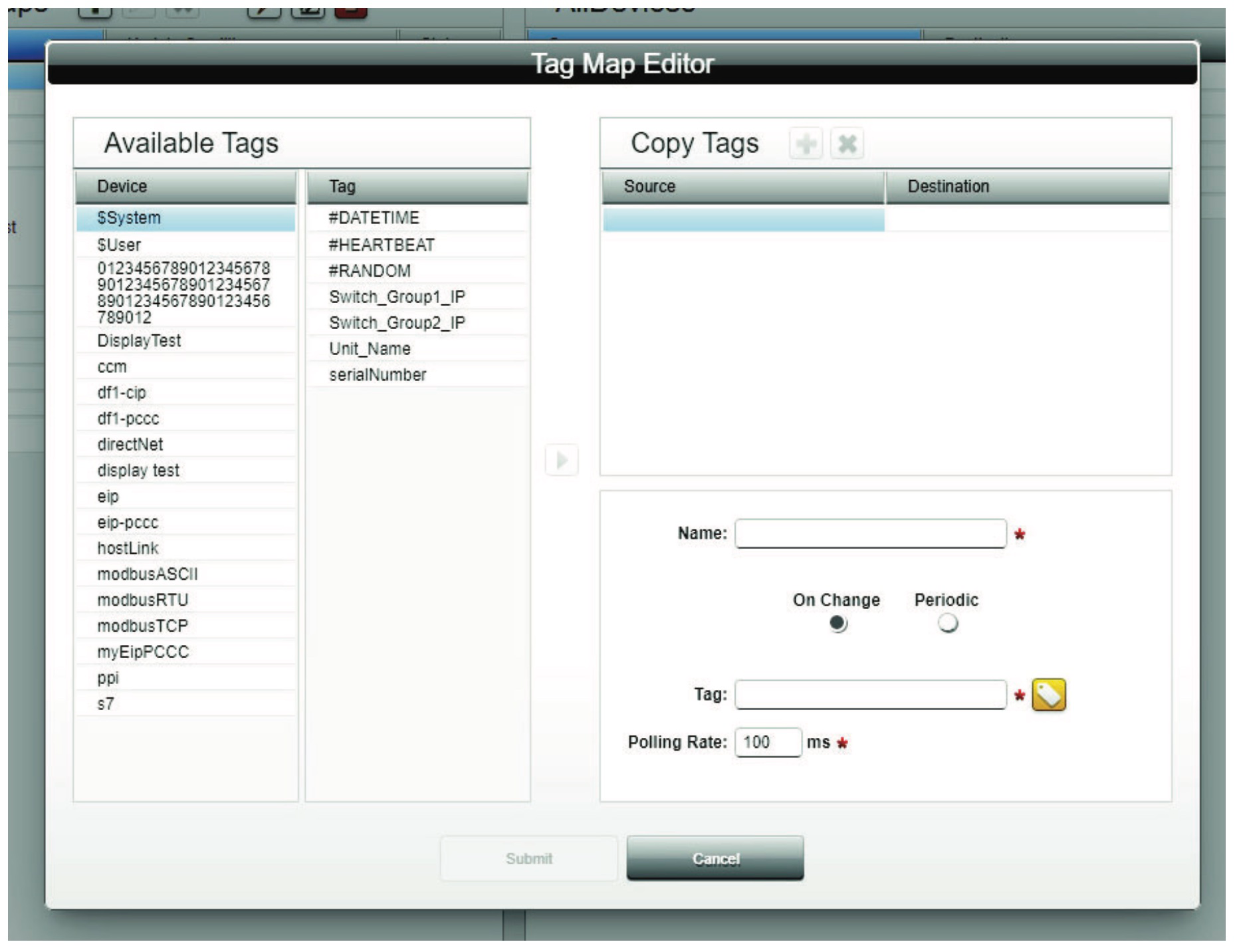
The final step in the process is to activate the tag map to initiate communication between the source and destination tags hosted on the network devices. A tag map viewer on the PC allows for a check that the right source data is heading to the right destination.
Conclusion
Industry 4.0 enhances manufacturing productivity and efficiency. However, it requires new Industrial Ethernet infrastructure, which is expensive and disruptive to install. As shown, industrial gateways allow for a staged introduction of Industry 4.0 by bridging the gap between existing RS-232/RS-485 networks and the phasing in of Industrial Ethernet infrastructure. Using these solutions, equipment and networks can be gradually upgraded over months or years with minimal disruption.