


The system is designed using the HV macrocells and other internal and external components to drive a 3V DC-DC motor as well as charging the battery. The proposed device is a rechargeable screwdriver, powered by a 3.7V Li-ion battery. The battery can be charged by any USB power adapter using implemented Constant Current – Constant Voltage (CCCV) charging method.
The device has two modes for motor direction, the Hold-to-Stop function with an extra Screw Tightening feature, andthe constant voltage on the brushed DC motor with overcurrent protection. Only one SLG47105 allows us to create a complete device with charging control, motor driving, overcurrent protection, and other interface features.
1. Operating Principle
The block diagram of the Rechargeable Electric Screwdriver is shown in Figure 1.
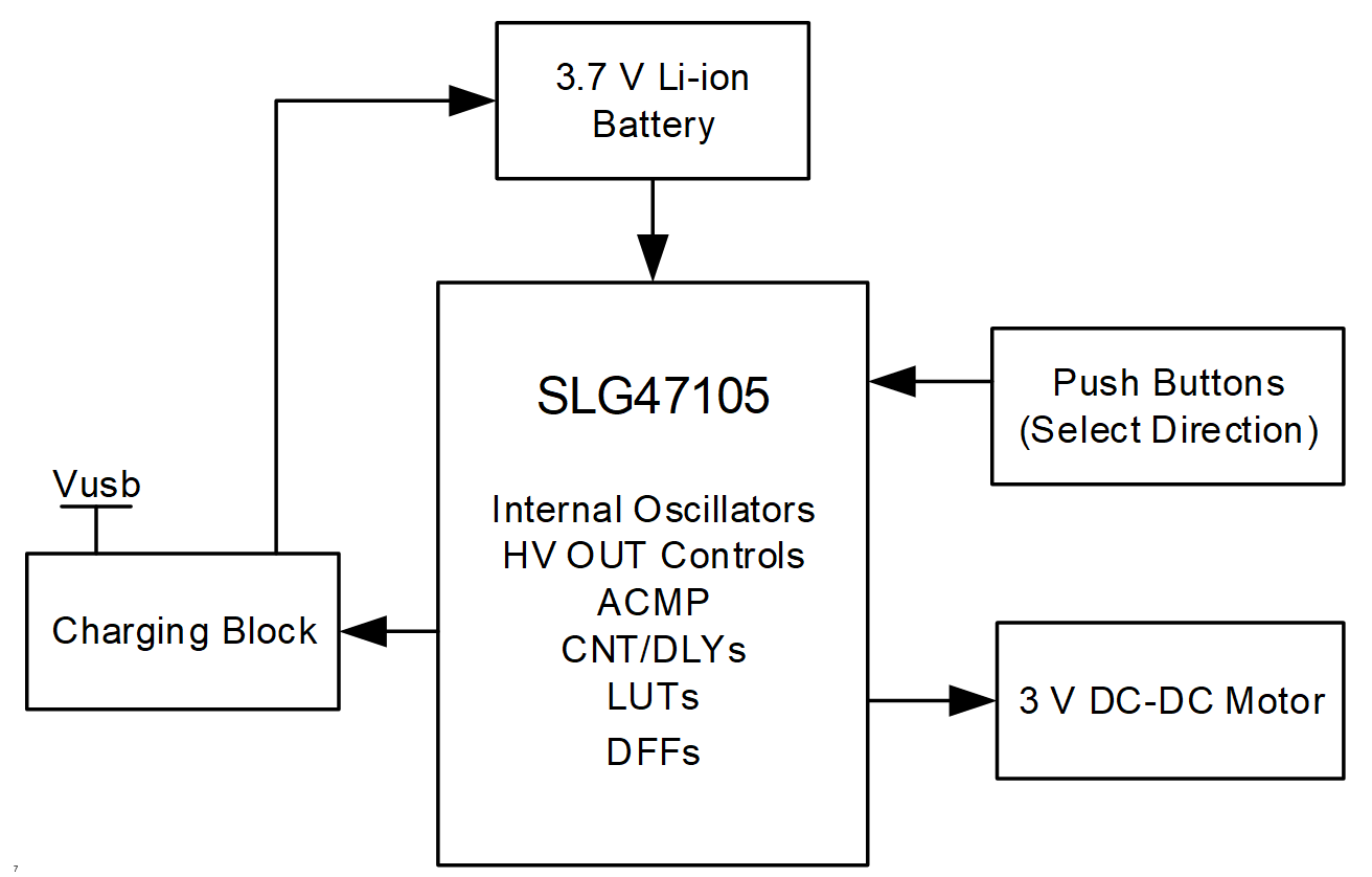
Figure 1: Block Diagram
The 3V DC-DC Motor with 200 rpm was selected to create a screwdriver. There are two push buttons to select the motor directionclockwise and counterclockwise for screwing and unscrewing, respectively.
The device is powered with a 3.7V Li-ion battery. When the USB charger is connected, the SLG47105 detects the voltage level and starts the appropriate stage of CC-CV charging begins.
The full circuit schematic is presented in Figure 2.
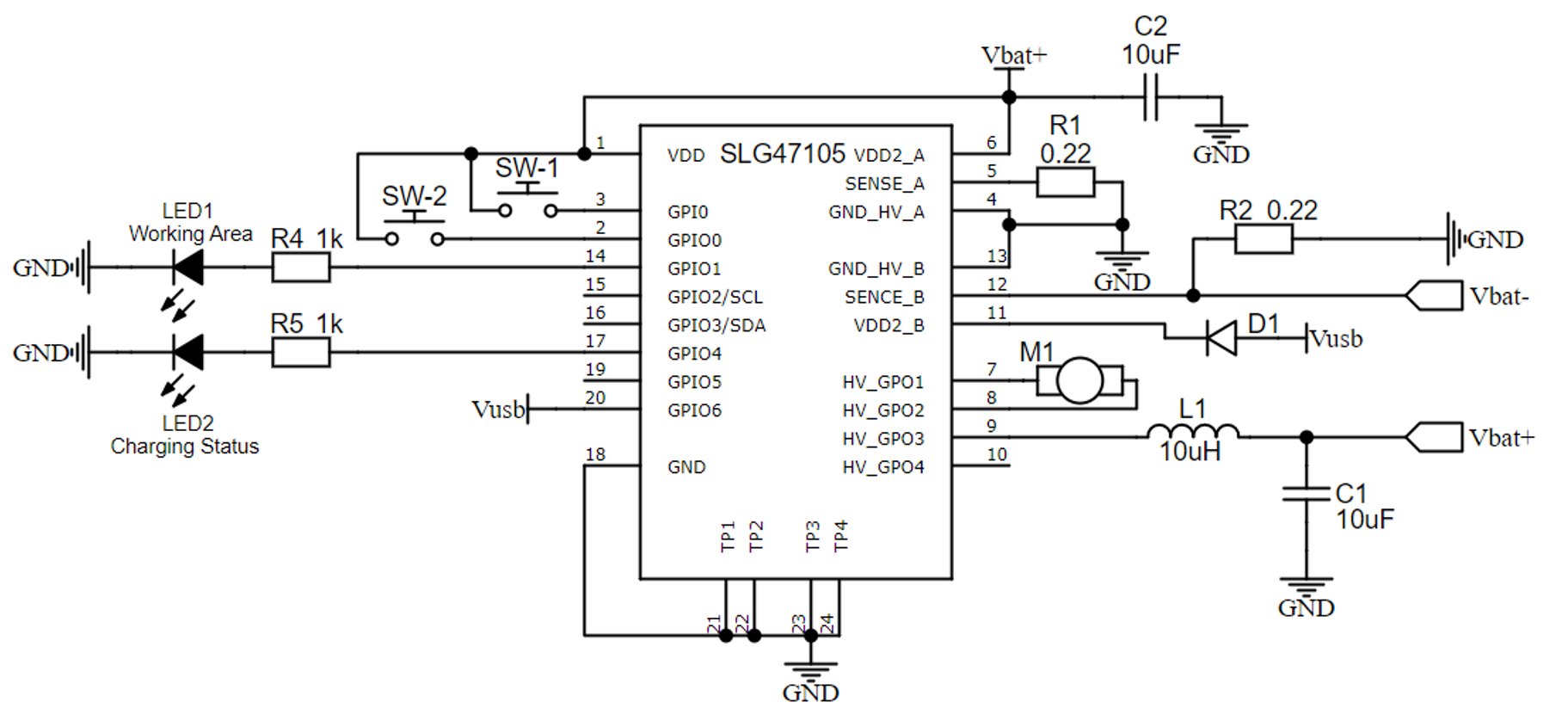
Figure 2: Full Circuit Schematic
There are also two LEDs to notify about the process. The LED1 (white) indicates the screwdriver working – the motor is ON. The LED2 (red) indicates the charging process: constant ON – charging, blinking – charging is complete.
2. GreenPAK Design
The GreenPAK design (free GUI-based tool) consists of two parts screwdriver motor and USB charging. The screwdriver motor part is shown in Figure 3. The design file can downloaded here AN-CM-364 Rechargeable Electric Screwdriver.hv.
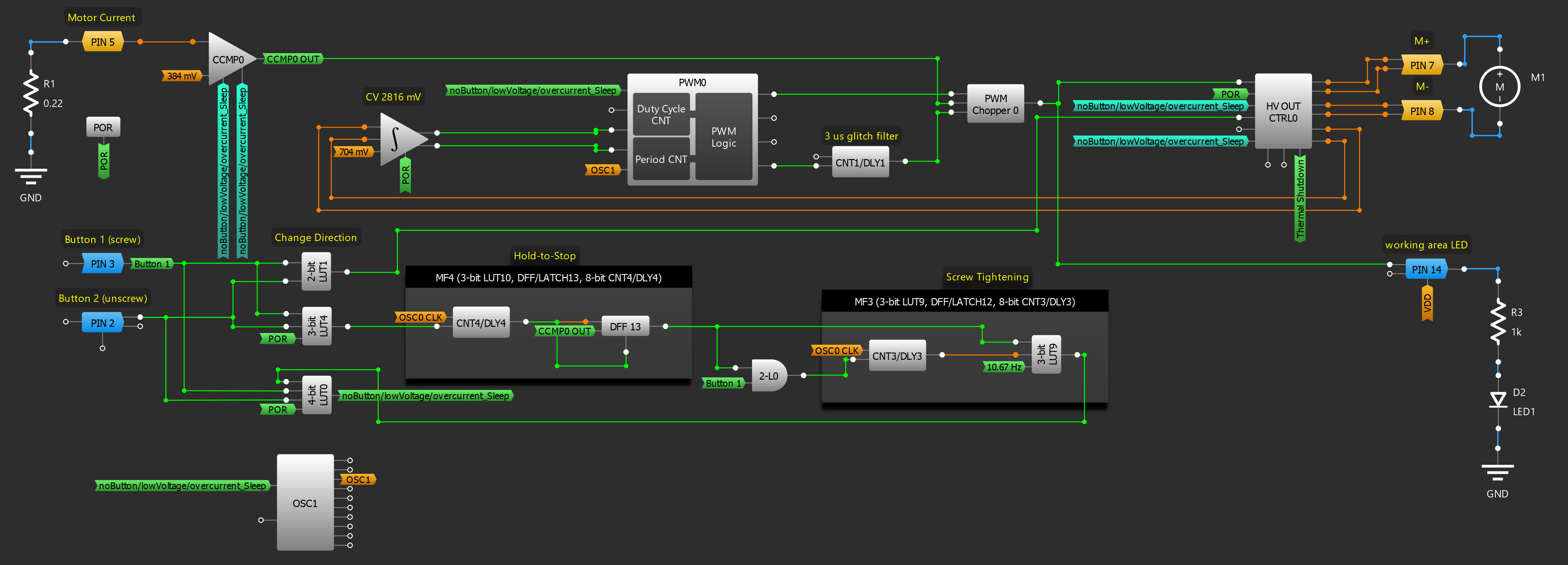
Figure 3: Screwdriver Motor GreenPAK Design
The PWM0 block provides a ~50kHz signal with a PWM depending on the load voltage at the motor. The Diff+ and Diff- of the HV OUT CTRL0 are connected to HV_GPO0_HD and HV_GPO1_HD of the Differential Amplifier with Integrator and Analog Comparator. This macrocell is useful when there is a need to keep the constant voltage at the Full Bridge load. Theintegrated DC voltage level is applied to the comparator`s negative input. The Differential Amplifier with Integrator and Analog Comparator outputs areused to control the PWMduty cycle. In this case, a closed loop system controls the PWM duty cycle to ensure the constant average output voltage level. Then the PWM0 signal goes to the PWM Chopper 0 macrocell. The CCMP0 checks the motor current, this signal goes to the Chop input of the PWM Chopper 0 macrocell. If it is higher than the maximum allowable current, the HIGH signal on the CCMP0 cuts the PWM0 signal decreasing the duty cycle. As a result, we have the same PWM0 signal but with a lower duty cycle to avoid overcurrent. The CNT1/DLY1 sets the 3us Blanking Time of the PWM Chopper 0.
To select a direction of the motor there are PIN2 for unscrewing and PIN3 for screwing that are connected to push buttons. 2-bit LUT1, 3-bit LUT4, and 4-bit LUT0 are used for selecting purposes and to power down the device if no button is pushed or two buttons are occasionally pushed at the same time. In addition, the MF4 macrocell is used for the Hold-to-Stop function with an extra Screw Tightening feature (screw mode) on MF3. This feature triggersfive ~10 Hz pulse signals to the motor during 500 ms to tighten the screw and then powers down the system.
The system works only when VDD is higher than 3V (ACMP1).
The USB Charger part is presented in Figure 4.
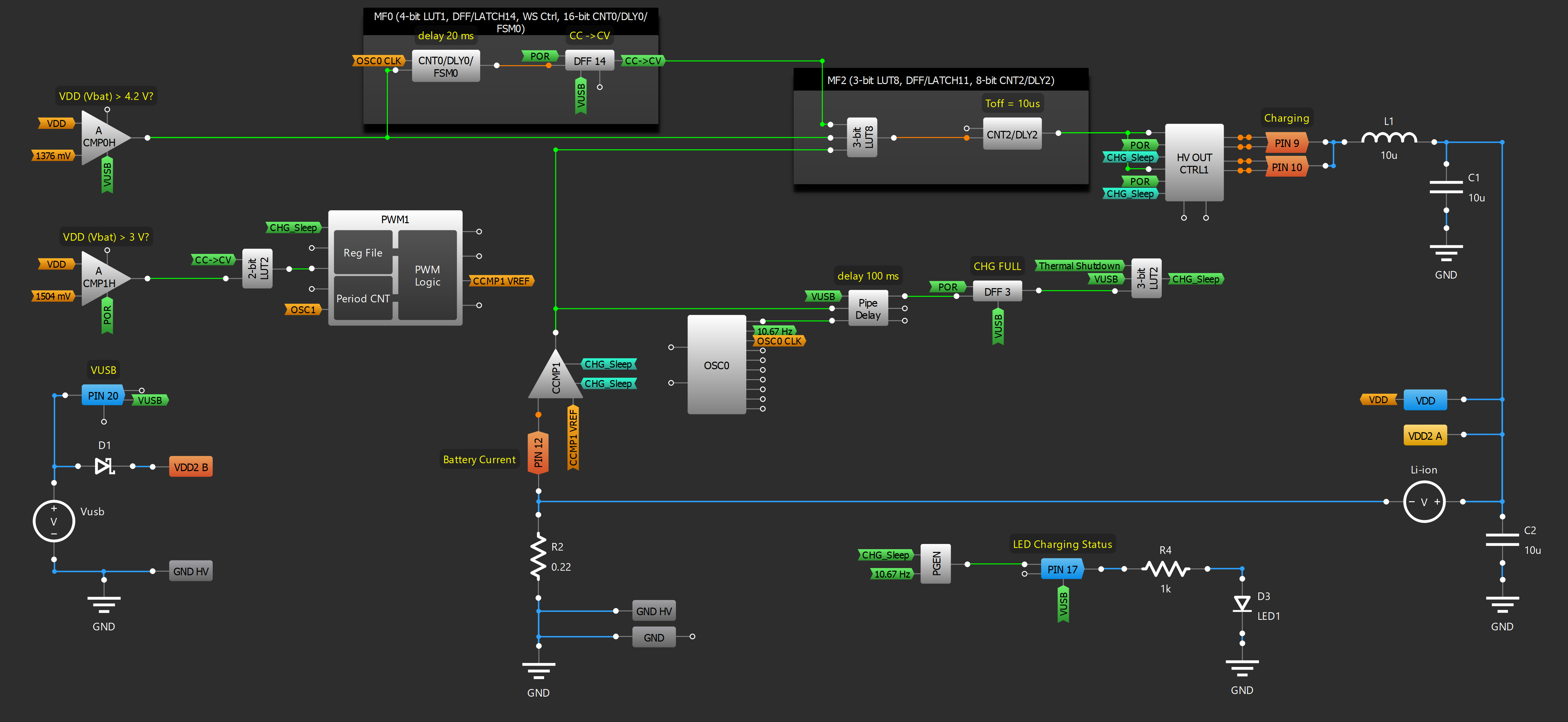
Figure 4: USB Charger GreenPAK Design
If the Vusb is connected, ACMP0 and ACMP1 check the VDD (Vbat) voltage. If this voltage is lower than 3V the Pre-charge starts. In this case, the Up/Down input of the PWM1 macrocell is LOW, which means that we start charging from 160 mV for CCMP1 Vref (Figure 5). As a result, the CCMP1 maintains the ~90 mA current.
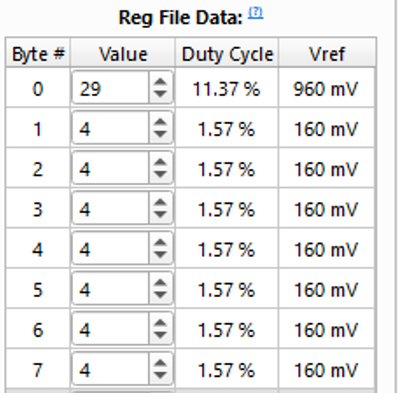
Figure 5: CCMP1 Vref Reg File Data
As soon as the ACMP1 output is HIGH (the Vbat is higher than 3 V), the Constant Current phase starts. In this case, the Up/Down input of the PWM1 is HIGH, so the CCMP1 Vref is 960 mV. The resulting current is ~550 mA. Note that these current limits can be changed by changing the Vref value in the Reg File or by changing the resistor R2 connected to the PIN 12 (Sense B).
This CC phase continues until the battery voltage reaches 4.2V (ACMP0 output is HIGH). Then the CC stops and the Constant Voltage phase starts. In this case, the ACMP0 controls the constant voltage of 4.2V and the CCMP1 just checks and keeps the current decreasing and lower than 90 mA until the battery is fully charged. When the battery is fully charged, the charging process stops and all corresponding blocks are in Sleep Mode -> CHG_Sleep is HIGH.
3. Device Testing
The following Figures 6-8show the signal on the motor terminal depending on VDD (Vbat).
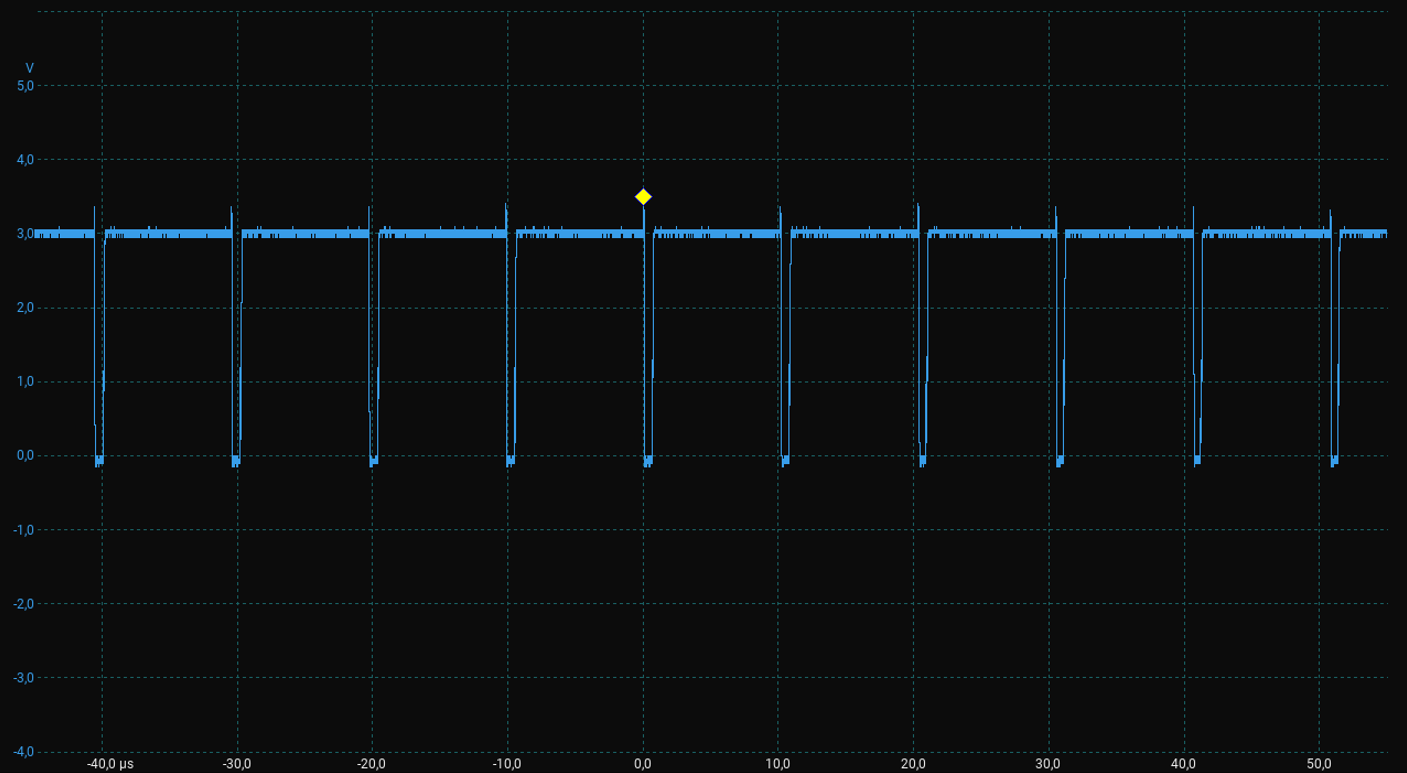
Figure 6: VDD = 3V, duty cycle 94%
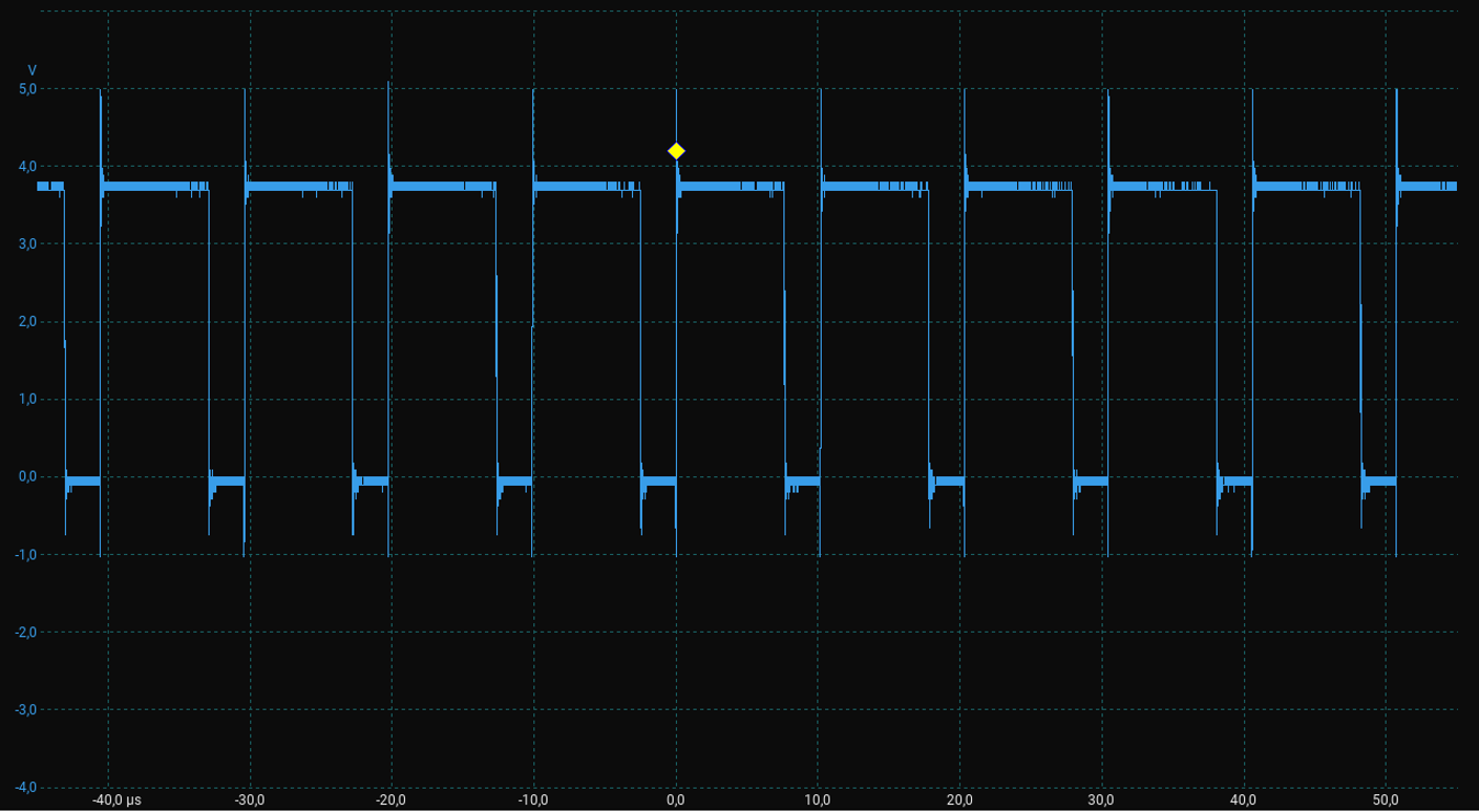
Figure 7: VDD = 3.7V, duty cycle 75%
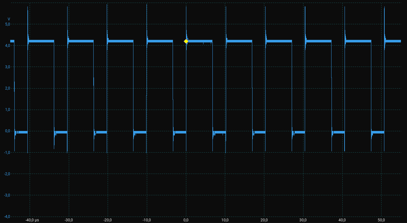
Figure 8: VDD = 4.2V, duty cycle 67%
Conclusion
This article describes how to configurethe HVPAK to create a rechargeable electric screwdriver. The results prove that the circuit works as expected, and the SLG47105 is capable of acting as the control module for the 3V DC-DC Motor and 3.7V Li-ion battery charger at the same time.
In addition, the device has two modes for motor direction, the Hold-to-Stop function with an extra screw tightening feature, andthe constant voltage on the motor. The SLG47105 internal resources, including the HV part, oscillators, logic, and GPIOs are easy to configure to implement the desired functionality for this design.