
SiC switches in motor drive applications
Patrick Baginski, Vincotech, takes a closer look at the benefits, impacts and limitations of SiC switches to the induction motor
Most modern variable frequency drives (VFDs) use pulse width modulation (PWM) pulse pattern with very fast-switching power semiconductor devices such as IGBTs, which are now the industry standard because of their reliability and low switching losses. With PWM inverters the output voltage is no longer a sine wave but a rectangle shape.
From time to time SiC switches have been discussed for drive applications because these are fast switching devices; switching speed can be increased and/or losses can be decreased. SiC components are also small and withstand high temperatures. They are faster than today’s IGBTs – reducing the switching losses dramatically and conduction losses can be also lower if the RDS(on) is low enough. Additionally the body diode has very negligible recovery losses. Further loss reduction can be achieved when the MOSFET channel is turned on in parallel to the conducting body diode and used in synchronous rectification mode.
There is potential for energy savings in motor drive application using SiC components, but a closer look to the complete application of VFD, motor cable and the induction motor will needed.
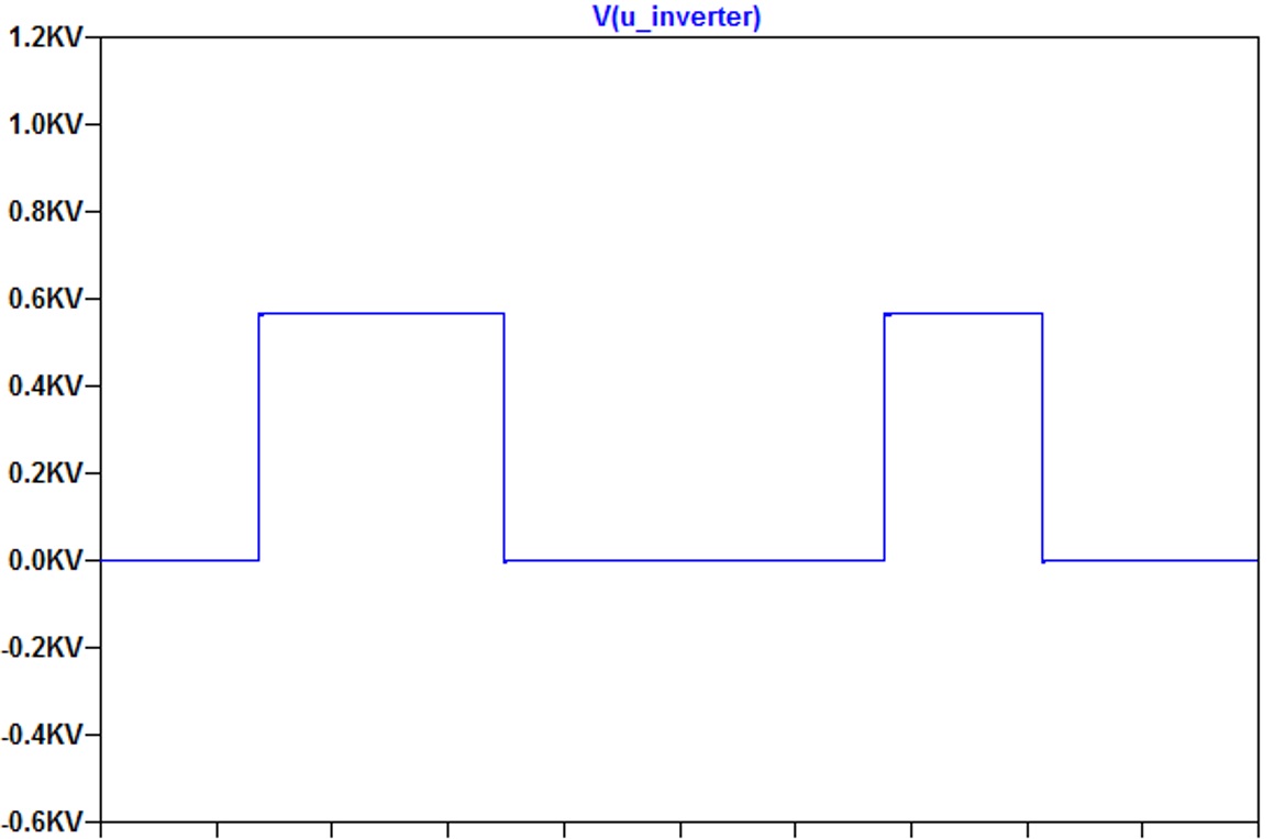 Figure 1: Output voltage of the inverter and voltage at motor terminals
SiC components usually have a higher power density compared to Si components and SiC switches have a body diode implemented so there might be no need for additional freewheeling diodes depending on the application requirements. The heatsink can also be smaller and lighter, due to the low switching losses and less dissipated heat.
Dead time is very important for a reliable operation. Too little dead time may cause shoot through, while an increase leads to higher total harmonic distortion (THD). Dead time introduces small voltage errors, which are sufficient to produce distorted motor currents, oscillations of the motor torque, potentially resulting in loss of motor control. As the switching times are much lower for SiC the dead time can be reduced resulting in less THD based on the same switching frequency than for Si switches. This would be true if there is no hard dv/dt requirement which most motor drive applications have.
If much higher voltages can be accepted the carrier frequency obviously can be increased to lower the ripple current and therefore the torque ripple. By increasing the pulse frequencies, the switching dead time takes a remarkable part of the whole modulation period and, thus distorts the average load voltage more seriously.
The minimum dead-time is given as follows:
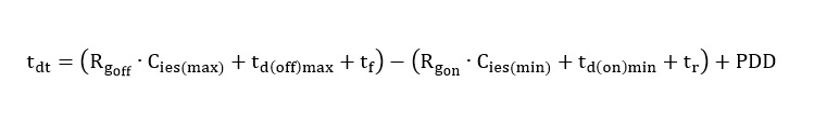
(PDD is defined as propagation delay difference and can be found in the manufacturer’s datasheet of the gate driver IC, tr = rise time during turn-on, tf = fall time during turn-off.)
Where optocouplers have been used before, more advanced drives come into play with inductive or capacitive coupling.
If a high carrier frequency is needed for drives with high output frequency in, e.g, high speed rotation machines, SiC components would be the right choice.
The drawback of SiC switches might be higher EMI caused by the high dv/dt and over-voltage shoots.
Motors and insulation
The most important component of an induction motor is the winding as it builds up the magnetic field inside the machine. The dielectric strength of the insulation material depends on the properties of the material, on the thickness, the rate of the applied voltage increase and the shape of the voltage versus time curve.
Faster rise times and higher voltage amplitudes have an impact to the usable life-time of the motor (see Figure 1).
The voltage at the motor terminals depends on the cable characteristics, cable length, switching speed of the semiconductor, motor impedance and the DC-link voltage inside the drive. Impedance mismatch causes voltage pulses to be reflected back, causing higher peak voltage.
Motor peak voltage and dv/dt must both be within the specified limits. As SiC components are fast these have to be slowed down when used for motor drive applications.
Often a motor cable is used between the VFD and the induction motor. The fast change of voltage generated by a frequency drive causes some increase in the voltage stress on the cable connection to the motor. Standard multi-conductor cables rated for 600V will most likely not meet the requirements of VFD applications and can cause operating malfunctions and early failures.
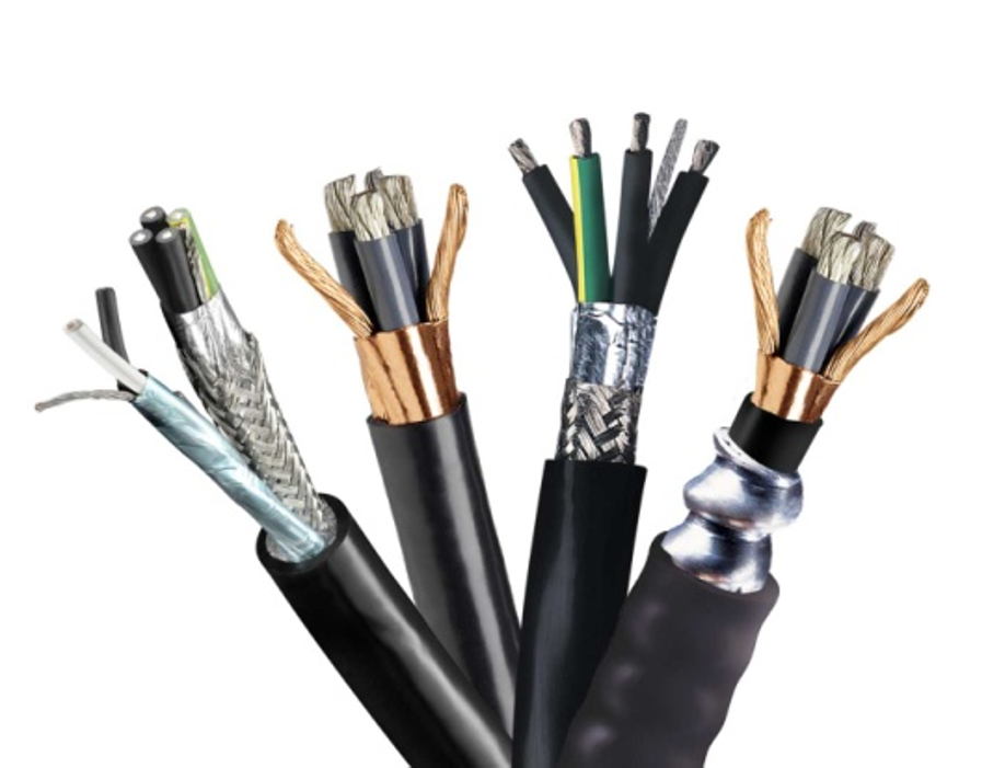 Figure 2: Special cable for VFDs and equivalent circuit of a cable
Figure 2 some special motor cables illustrated that are often used for motor drive applications together with VFD.
These elements influence the velocity propagation of a cable:

where c = speed of light 299792458 m/s; µr = 1 for cable insulations; εr = permittivity of the dielectric material between conductors; = Inductance of the cable per length in Henry;
= Capacitance of the cable per length in Farad.
It is important to indicate the cable length and the critical cable length in a VFD application. At this length, the voltage on the motor terminals will be twice the DC-link voltage because of a reflected wave.
Another important parameter is the switching speed of the semiconductor. The critical cable length is given when a new pulse from the inverter starts before the reflected voltage wave from the motor terminal has travelled back to the inverter’s output. With modern components this happens with cable length between 25 to 50m.
Mismatch between the cable impedance and the motor impedance cause some reflection. Small motors with 1 kW power have an impedance in the range of 1kΩ whereas lager motors of a few 100 kW show impedance values of roughly 100Ω.
The reflection coefficient is given by
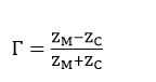
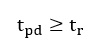
It has to be differentiated between two cases. The propagation time is less than the turn-on rise time and the propagation time is equal to or more than the turn-on rise time
When the cable is shorter than the critical length, the reflecting voltage front has travelled to the motor and back to the inverter before the voltage at the output of the inverter changes. In this case the backward travelling wave voltage can be calculated as:
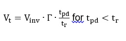
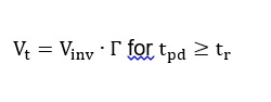
For long cables, which means that the wave did not travel back to the inverter’s output, the backward travelling wave voltage is calculated by:
Windings
The dielectric properties of a material are the characteristics that make the material an electrical insulator rather than a conductor. A voltage across the thickness of an insulation material causes dielectric stress. If the voltage is exceeded it can fail suddenly. Other stress like thermal, mechanical and vibration also decrease the ability to withstand dielectric stress.
How windings are arranged inside the motor has a strong influence on the voltage across the insulation. If the first and the last turn of the windings on the left hand side are far away from each other which leads to a much lower stress compared to the randomly winding where the first turn and the last turn could be directly located to each other.
A winding fails when the dielectric strength of the insulation can no longer support the operating voltage or transient over-voltage seen during start-up or shut down.
Standard motors and motor designed for VFD operation are limited in the voltage rise steepness as well as in the peak voltage.
Bearings inside the motor can also suffer due to fast switching together with the high carrier frequencies, which can lead to pulse currents in the bearings and to a discharge following a slow erosion of the racings. This electric discharge machining (EDM) happens when the bearing voltage is greater than the breakdown voltage of the lubrication film. The bearing currents depend on the size / power of the motor and how the motor housing and the rotator is grounded. The type of motor cable and the correct connection of the ground wire and the shield have a very high impact. Finally, the amplitude of the bearing currents is as higher as the switching speed, carrier frequency and the DC-link voltage.
Conclusion
SiC components are of great interest to improve system efficiency and in applications where a high output frequency is needed as the dead time can be shorter than for Si components.
Motor drive applications have hard dv/dt requirements and SiC switches need to be slowed down to achieve this. Until difficulties for the motor insulation and bearing currents have been solved, SiC switches will be limited to markets where a high power density is needed, compactness matters or where the drives are mounted close to the motor. The limiting factor is not the semiconductor but the system behind it.
Visit Vincotech – Hall 9-310
Product Spotlight
APV1111GVY
Panasonic

Panasonic PhotoMOS® Photovoltaic MOSFET High-Power Drivers
| SKU: | |
|---|---|
| Stock: | 3490 |
| Cost: | $3.95 |
