
Power supply sequencing simplified
The challenges in designing a multiple power supply multiply with each additional supply rail, says Nathan Enger, senior applications engineer, Linear Technology
The designer must consider the dynamic environment of co-ordinated power supply sequencing and timing, generating power-on reset, monitoring for faults and responding appropriately to protect the system. An experienced designer recognises that flexibility is key to successfully navigating the ebb and flow as a project moves from prototype to production. The ideal solution minimises the number of hardware and software changes during development.
The optimal multi-supply design tool is a single IC that resides in a design from beginning to end, requiring no wiring changes through the life cycle of the product. It autonomously supervises and sequences multiple power rails, co-operating with other ICs to seamlessly supervise many power regulators in the system, and provides fault and reset management. The designer can use powerful PC-based software to configure, visualise and debug system behaviour in real-time when connected to an I²C bus.
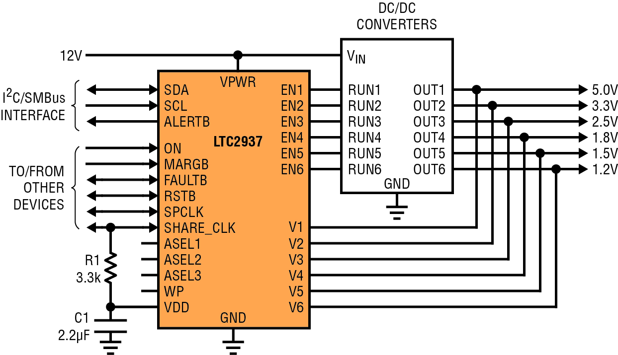
Figure 1: LTC2937 sequencing six supplies
The LTC2937 is a six-channel voltage sequencer and high accuracy supervisor with EEPROM. Each of the six channels has two dedicated comparators to monitor over- and under-voltage conditions to within ±0.75%. The comparator thresholds are individually programmable over a range of 0.2 to 6.0V with 8bit resolution. The comparators are fast, with deglitched propagation delays of 10μs. Each sequencer channel has an enable output that can control an external regulator, or the gate of a pass FET. All aspects of supervisor voltage and sequencer timing are individually configurable, including up- and down-sequence order, sequence timing parameters, and fault response. The built-in EEPROM makes the part autonomous and able to power-up in the correct state to control the system. Multiple LTC2937s can co-operate to autonomously sequence up to 300 supplies in a system, all using a single-wire communication bus.
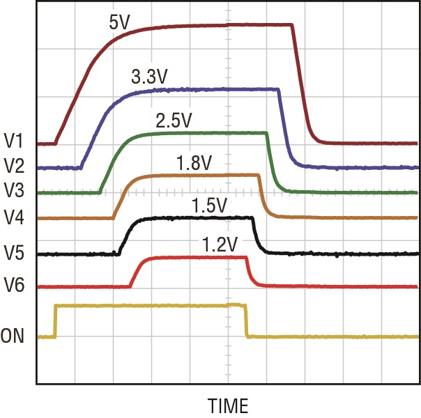
Figure 2: Power supply sequencing waveforms
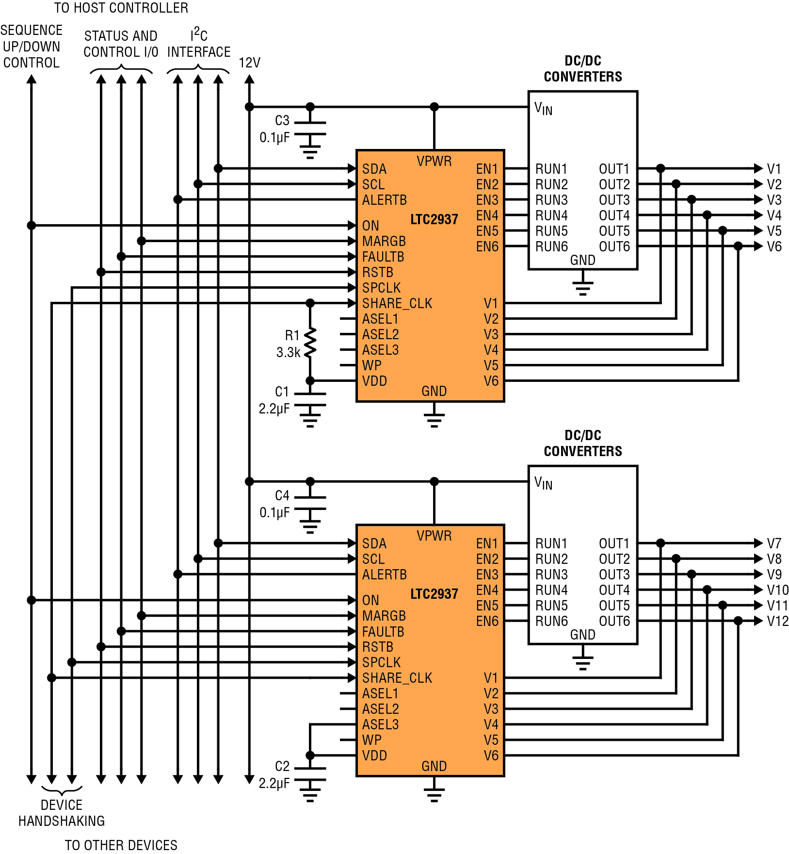
Figure 3: Typical connections between multiple LTC2937s
Power supply faults are controllable, visible and manageable through the autonomous fault response behaviours, and through debug registers. The sequencer automatically detects fault conditions and can power down the system in a co-ordinated manner. It can remain off, or attempt to resequence the supplies after the fault. In a system with a microcontroller and an I²C/SMBus, the LTC2937 provides detailed information regarding the type and cause of the fault, and the state of the system. The microcontroller can make decisions about how to respond, or allow the LTC2937 to respond on its own.
Three steps of supply control
A power supply cycle has three operating steps: sequence-up, monitoring and sequence-down. Figure 2 shows these phases for a typical system. During up-sequencing, each power supply must wait its turn, and then power up to the correct voltage in a designated amount of time. During the monitoring phase, each power supply must remain within designated over- and under-voltage limits. During down-sequencing, each supply must wait its turn (often in a different order from up-sequencing), then power down within a configured time limit. At any point, something can go wrong, causing a fault in the system. The design challenge is to create a system in which all of these steps, and all of the variables, are easily configurable, but carefully controlled.
Sequence-up begins when the on input transitions to active. The LTC2937 advances through its up-sequence, enabling each supply in turn, and monitoring to ensure that the supply voltage rises above the configured threshold before the configured time. Any supply that fails to meet its assigned timing triggers a sequencing fault.
The sequence position clock allows the devices to share sequence position information. Each channel is assigned to a sequence position (one to 1023), and receives its enable signal when the LTC2937 counts to the given number in the sequence. A channel with sequence position one is always enabled before a channel with sequence position two. If a system specification changes, requiring these two channels to sequence in a different order, then the sequence positions can be swapped, powering the second channel in sequence position one, and the first in position two. Multiple LTC2937s can share sequence position information, so that sequence position N happens at the same time for all, and channels controlled by different chips can participate in the same sequence (see Figure 3).
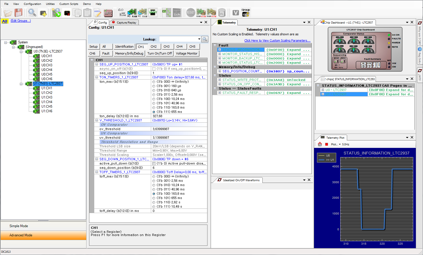
Figure 4: The LTpowerPlay GUI displays the status and debug register information in one convenient interface
The monitoring phase begins when the last channel sequences up and crosses its under-voltage threshold. During monitoring, the sequencer uses its high accuracy comparators to continuously monitor the voltage at each input against over- and under-voltage thresholds. It ignores minor glitches on the inputs, only triggering if the voltage crosses the threshold with sufficient magnitude for sufficient time. When the LTC2937 detects a fault, it responds immediately according to its configured supervisor fault response. In a typical scenario, it shuts down all supplies simultaneously, asserting ‘resetB’ to the system, then it attempts to resequence according to the normal start-up sequence. This prevents the supplies from powering parts of the system while others are unpowered, or executing an unco-ordinated recovery after the fault. Multiple sequencers in a system can share fault state, and respond to each other’s faults, maintaining coherence between co-operating channels during fault recovery. The LTC2937 offers numerous programmable fault response behaviours to satisfy different system configurations.
The sequence-down phase begins when the on input transitions low. The sequence position clock counts again to bring the supplies down, but all of the sequence-down parameters are independent from the sequence-up parameters. Channels can sequence down in any order, and multiple LTC2937 chips co-ordinate sequencing of all controlled supplies. During the down-sequence, each supply must fall below its discharge threshold within its configured time limit, or trigger a sequencing fault. The LTC2937 can pull down on the supply with an optional current source to actively discharge slow moving supplies.
The sequence position clock enforces event-based sequence order for time-based sequencing in systems that enable supply rails at pre-determined time points. Reconfigurable registers function in either time-based or event-based mode.
Information exchange
The LTpowerPlay GUI displays the status and debug register information. It communicates with any power system management IC from the company on the I2C/SMBus.
LTpowerPlay saves settings on the PC, and can write them into the LTC2937 EEPROM. The GUI also shows all of the debug information for system malfunctions. It can show when any supply is over- or under-voltage, or if a supply has failed sequence timing. After a fault, the GUI allows control over restarting the system.
The LTC2937 simplifies power system sequencing and supervision and can operate on its own, or in concert with other chips in a large system, orchestrating the operations of up to 300 power supplies.
Product Spotlight
APV1111GVY
Panasonic

Panasonic PhotoMOS® Photovoltaic MOSFET High-Power Drivers
| SKU: | |
|---|---|
| Stock: | 3490 |
| Cost: | $3.95 |
