
Driving piezoelectric transducer buzzers
Forming part of the user interface apparatus, piezoelectric transducer buzzers can provide an important function in a broad array of electronic equipment. Through incorporation of one of these electromechanical components, an audible signal can be passed to the equipment’s user.
By Ryan Smoot, CUI Devices
This can serve as a way of initiating a user response (alerting them if an action needs to be done), providing feedback (to confirm that a procedure has been carried out), or warning them of a problem that is arising.
Transducers vs. Indicators
Piezoelectric transducer buzzers are able to deliver higher sound pressure levels (SPLs) than magnetic indicator buzzers, but they need external drivers in order to excite a signal. Although this does call for some additional design effort, access to an external driver means that piezoelectric transducer buzzers are able to support a greater variety of tones and sounds.
In contrast, magnetic indicator buzzers each have a built-in oscillator, making for simplified design integration at the cost of more limited tones.
Analysing the Trade-offs of External Driver Circuits
|
Driver Type |
Main Advantages |
Main Disadvantages |
|
Rudimentary |
Low component count and low bill-of-materials costs |
Power losses impinge on buzzer output |
|
Buffers Included |
Enables some output improvements |
Adds to costs |
|
Reversed Buffers |
Increases voltage applied to buzzer |
Adds to complexity |
|
Full-Bridge |
Markedly boosts output without increasing costs |
Slightly less efficient than previous arrangement, due to greater power losses |
|
Resonant |
Improved overall system efficiency |
Limitations on the buzzer tones supported and bulkier (due to inductor) |
Table 1: Overview of the different external driver arrangements for piezoelectric transducer buzzers
An example of the most rudimentary piezoelectric transducer buzzer driver circuit is illustrated in Figure 1. This comprises the following elements - a reset resistor and a transistor-based switch (for example a BJT). With a small component count and minimal bill-of-materials costs, this provides a straightforward method via which to drive a buzzer. However, it should be noted that power dissipation across the reset resistor will have an impact on buzzer performance.
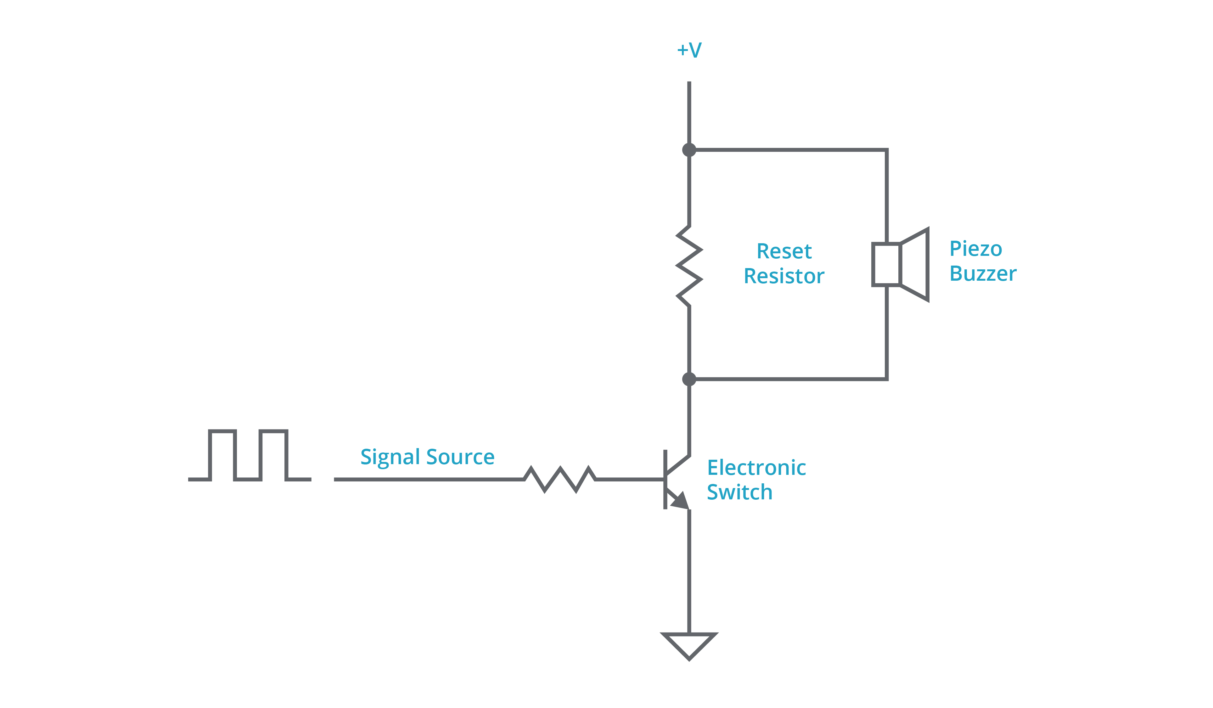
Figure 1: Rudimentary driver circuitry for a transducer buzzer
In order to address the power losses across the reset resistor, further modifications can be made to the circuit described in Figure 1. Inclusion of a pair of buffer transistors (as seen in Figure 2) will permit a higher impedance reset resistor to be employed. Losses can subsequently be reduced, allowing for the buzzer’s performance to be raised to some degree. Unfortunately, it results in less of the voltage being applied directly to the buzzer, while also adding to the associated costs.
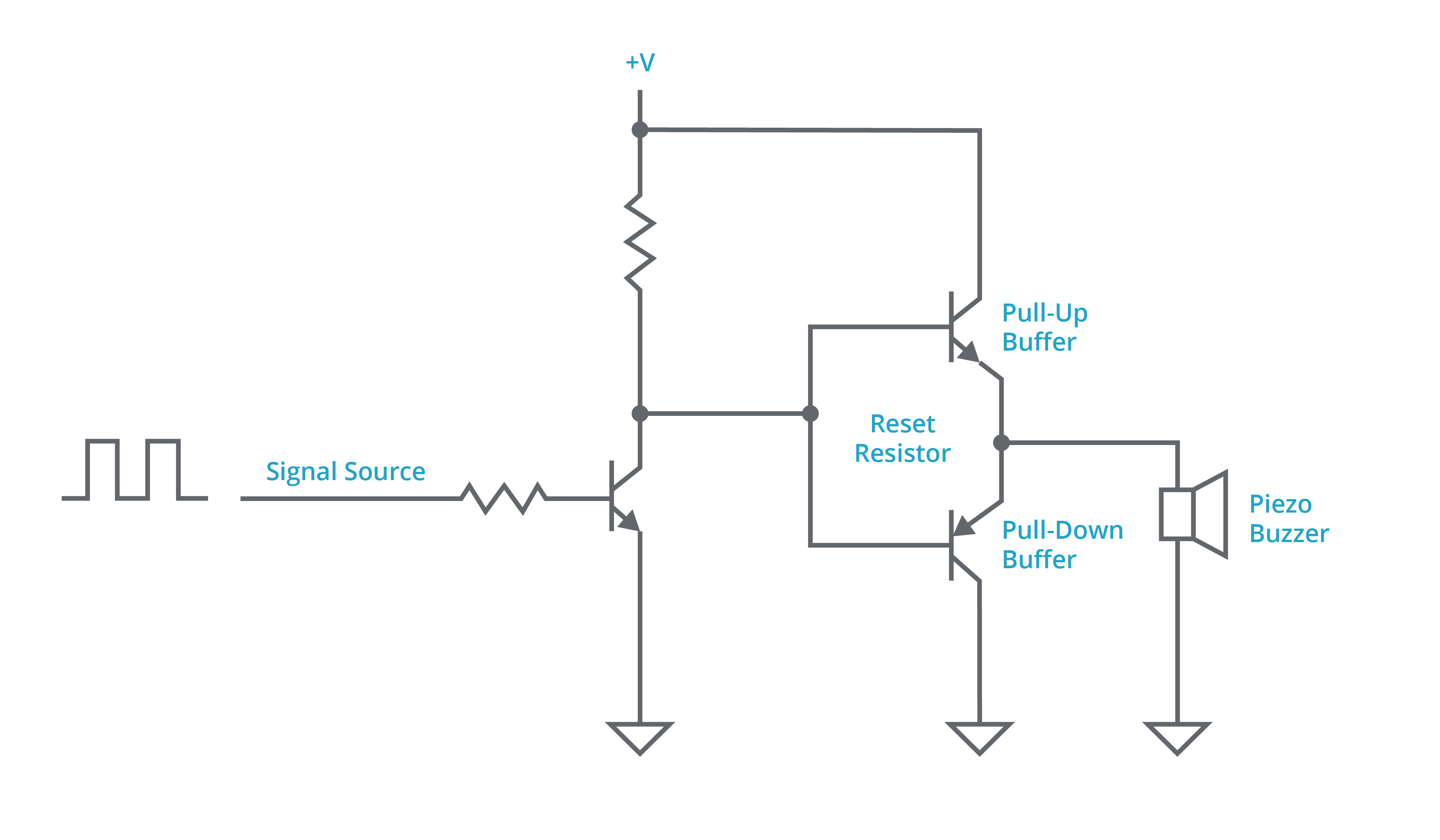
Figure 2: Addition of transistor-based buffers to the driver circuit
In situations where this lowering of the applied voltage is likely to be problematic, then reversing the orientation of the buffer transistors is recommended (to present a push-pull arrangement). BJTs or FETs can be used in either case with both of these configurations outlined in Figure 3.
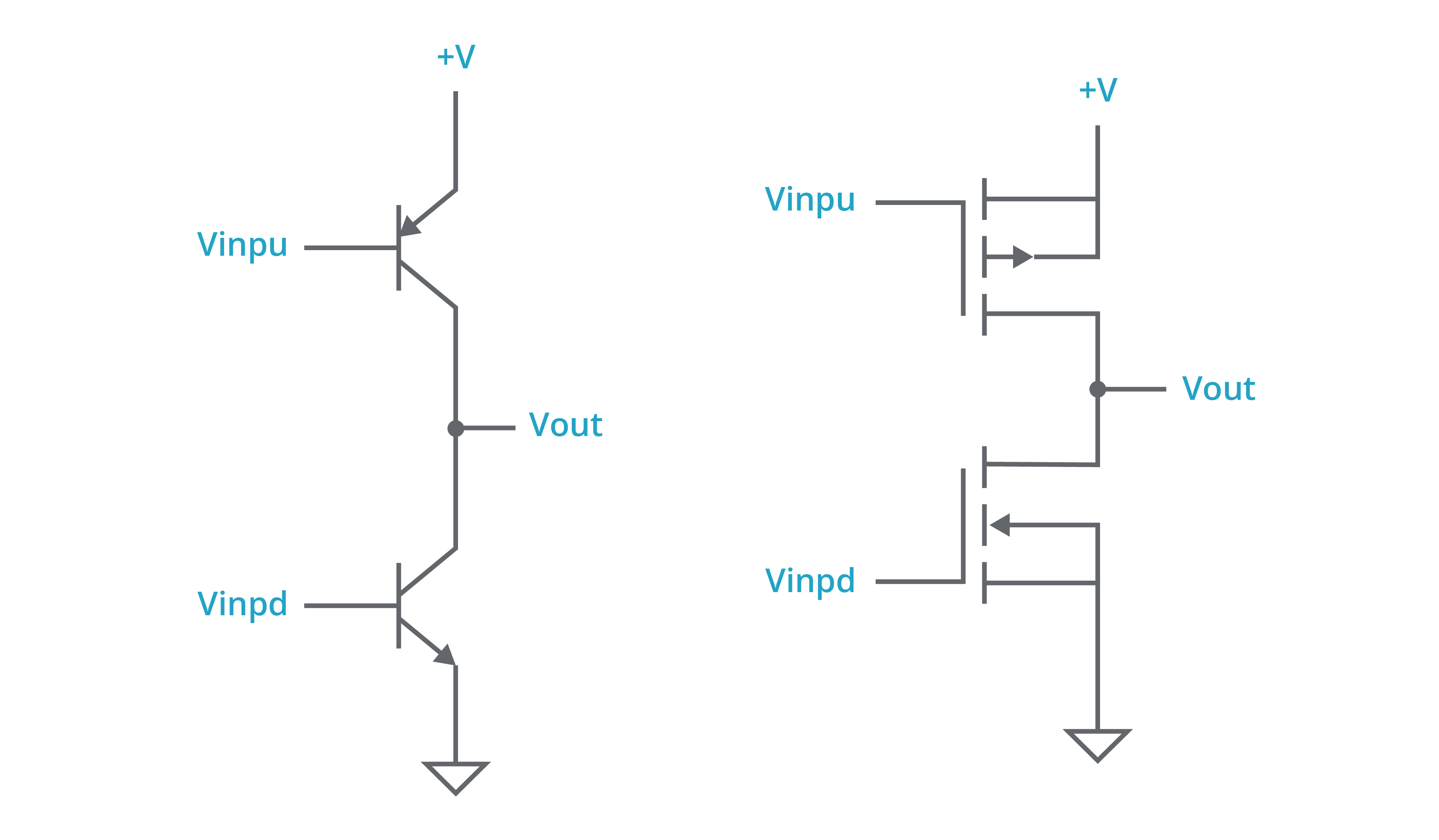
Figure 3: Circuit with reversed buffers - BJTs (left), FETs (right)
Instead of the half-bridge driver arrangements covered in Figure 3, it may be advisable to consider a full-bridge arrangement, where two half-bridge drivers are driven out of phase with the buzzer connected between the two half-bridge outputs. Through utilisation of a full-bridge arrangement, the voltage applied to the buzzer will be double the possible for a half-bridge driver arrangement. The output performance of the buzzer is thus boosted considerably. As full-bridge driver IC solutions are available, it is no longer necessary to rely on discretes. Consequently, such implementations are relatively simple to undertake and the costs involved are not particularly large either.
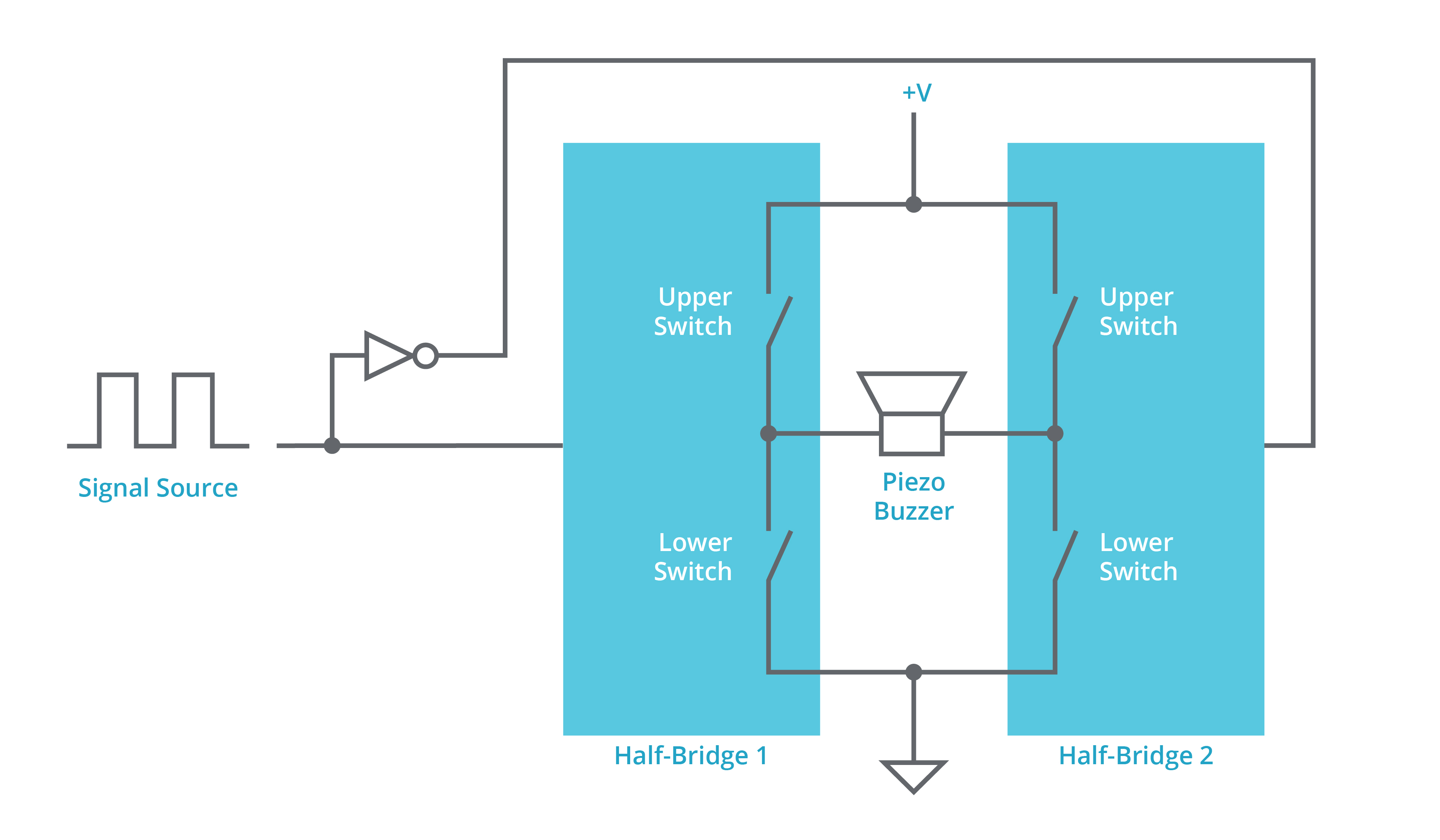
Figure 4: An example of a full-bridge buzzer driver
The final option to discuss is the resonant driver circuit (see Figure 5). Here a discrete inductor and the transducer buzzer’s own parasitic capacitance are utilised, with energy being built up and passed from one element to the other. The main advantages of a resonant driver circuit are that they offer elevated efficiency levels and enable a voltage to be applied to the buzzer which is beyond that of the supply voltage. In addition, they are very easy to implement. However, opting for a resonant circuit will put frequency restrictions onto the system, so the scope for varying buzzer tones will be impacted. Additional work may also be needed to match the frequency with the particular characteristics of the buzzer.
Figure 5: Example of a resonant driver arrangement
Conclusion
There are positive and negative attributes associated with each of the driver arrangements described in this blog. Which one proves itself most appropriate will be dependent on the specific task it is expected to perform and the nature of the sound output that should be generated.
Through CUI Devices’ expansive portfolio of buzzer solutions, with a range of voltage ratings, SPLs, and mounting styles, all of these different arrangements can be met to meet an engineer’s specific design requirements.
Product Spotlight
APV1111GVY
Panasonic

Panasonic PhotoMOS® Photovoltaic MOSFET High-Power Drivers
| SKU: | |
|---|---|
| Stock: | 3490 |
| Cost: | $3.95 |
