
Streaming HD
Designed around wireless peer-to-peer technology, Miracast could be much more than a simple cable replacement. By Dr. Iain Hunter, System Applications Engineer, Wireless Connectivity Solutions at Texas Instruments.
It is a term that has become more common since it was ratified in September 2012, and adopted by Google in the Android 4.2 release as an alternative solution for the distribution of High Definition video and audio from smartphones.
Miracast is the certification name for devices that meet the Wi-Fi Display specification (Wi-Fi Alliance), which describes how High Definition audio video material (1080p) can be streamed between a Source and a Sink device. It was conceived as a Wi-Fi based HDMI cable replacement for the consumer market so that, for example, video content on a smartphone could be seamlessly displayed on a TV. Implicit in the role as in HDMI cable replacement is the support of HDCP (High Definition Content Protection) to control the distribution of protected content.
It is built upon the Wi-Fi Peer-to-Peer specification which allows two Wi-Fi enabled devices to be directly connected together in a Peer to Peer (P2P) fashion without the involvement of an Access Point (AP). P2P mode is the replacement for the original Wi-Fi Ad Hoc mode in which one device in the network is defined to be the Group Owner (GO) and essentially provide AP functionality to the rest of the Client devices.
A critical feature of the Wi-Fi Display specification is that it does not define an overall system for the creation, distribution and display of audio/visual material. It only defines how the link between the Source software component — which is transmitting the content — and the Sink component — which is receiving it — will operate. The specification covers how the two Wi-Fi P2P devices will negotiate the link, how the content should be formatted and how it is transmitted, as shown in Figure 1. It does not define what the content is or how it is ultimately used. Additionally the specification defines a User Interface Back Channel (UIBC) which allows mouse or touch screen events on the Sink device displaying the content to be communicated back to the Source as control events, which opens up many more applications than simply replicating the Source’s screen.
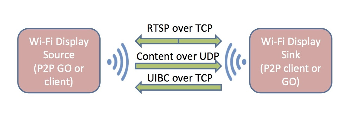
Figure 1: Wi-Fi Display architecture
Wider distribution
This means that the content does not need to be on the screen of the Smartphone; it could equally be content that is saved on the phone and streamed using Wi-Fi Display without being displayed on the screen of the source itself. Alternatively it could be the content from only part of the phone’s display, such as a mapping application. This opens up many more application areas and use cases than just replicating a phone’s display. If the content is not in the H264 video or the audio formats defined in the Wi-Fi-Display specification then it would need to be transcoded by the phone before delivery to the sink component.
The initial step is the creation of a P2P link between two devices, with one device acting as the P2P GO and the other as a client. Once this has been done each device can be allocated an IP address and existing TCP or UDP mechanisms can be used. Wi-Fi Display does not create any new protocols, what is does do is define new control messages and reuses standard RTSP over TCP methods to exchange them. The Sink and the Source exchange their capabilities such as resolution, codec format and whether the Source requires the content to be encrypted with the exchanged HDCP key. On successful completion of this negotiation the Source starts streaming the H264 video and/or AAC/LPCM/AC-3 audio in an MPEG2 TS encapsulation over RTP over UDP. The Sink will listen for UDP packets on a specific port and then decode and play the stream.
As Wi-Fi Display only describes how to handle the transfer content rather than how to build a complete system, it will typically be integrated into an OEM’s own application or as part of a higher layer application, such as the Car Connectivity Consortium’s Mirrorlink which will include it as an option by the end of 2013. Mirrorlink is a standard that defines how a smartphone can connect to a In Vehicle Infotainment (IVI) system.
The original consumer case of using an HDMI dongle to share smartphone content with a TV is the closest to a self contained Wi-Fi Display system and so will typically be best implemented using an ASIC solution.
More complex implementations that are integrating Wi-Fi Display as an additional function into an existing system will require a processor and Wi-Fi device combination that can efficiently implement the Wi-Fi stacks and video encode or decode functionality with minimal impact on existing functions. This requires a Wi-Fi device that will allow existing Wi-Fi Station functionality to continue in parallel to the P2P mode (concurrent mode), will minimise the interrupt load on the processor by offloading some of the packet processing and a processor that has the hardware accelerators and memory bandwidth to handle the video. Texas Instruments offers system solutions for both the Wi-Fi and processor to meet these needs.
The WiLink8 family of devices are single chip wireless combo devices that support Wi-Fi (802.11n, 2.4GHz and 5GHz), Bluetooth (BT), Bluetooth Low Energy (BLE) and ANT with the option of an Automotive qualified Q100 version. They have an internal coexistence and prioritisation mechanism that manages the competing accesses to the air interface between Wi-Fi and BT, to optimise their individual throughputs and maintain quality of service. This is important in an audio/video distribution context where the content may be received over Wi-Fi but then the decoded audio is streamed over BT using A2DP to headphones or speakers. A key feature behind the low host overhead of the WiLink8 Wi-Fi is the use of internal memory in the device to buffer up data packets and thus minimise the number of interrupts received by the host and the impact of the Wi-Fi on the existing system. This is illustrated by Table 1 which shows the effect of buffering in minimising interrupt handling on OMAP5 (running at 1.5GHz). These tests were carried out using the network testing tool, iperf, using the command-line tool, mpstat, to measure the load.
|
UDP Rx Rate (Mbit/s) |
Interrupts/s |
Data Transferred (bytes) /interrupt |
CPU Load % |
|
5 |
121 |
4933 |
1.9 |
|
10 |
77 |
13891 |
3.0 |
|
20 |
97 |
24278 |
5.0 |
|
40 |
119 |
37900 |
6.1 |
Table 1: The effects of buffering
Additionally, the WiLink8 devices are able to support concurrent operation, which allows Wi-Fi Display either as a P2P Group Owner to be added to a product’s existing Wi-Fi Station functionality or as a P2P Client to be added to an existing AP functionality. WiLink8 drivers are available for Linux, Android or QNX.
The Remote Media Display Reference Design is based on a DM8134 processor with a Cortex A8 at 600MHz and a 1080p60 capable video accelerator and WiLink8. This Reference Design makes use of the processor’s flexibility to provide solutions that require 1080p60 video, or the ability to sink multiple Wi-Fi Display Sources and composite them on the screen or low latency down to 120ms glass to glass from a low latency Source. Using a Google Nexus4 phone (running JellyBean 4.2 or 4.3) it will handle the 720p30 stream at 5Mbit/s with a 40% load on the A8 and a glass to glass latency of 350ms (over 200ms of which is due to the Nexus4 Source implementation). This reference design uses an optimised gstreamer pipeline to minimise the latency in decoding the RTP stream. The Reference Design is available from TI Eco-System partners.
For Automotive Infotainment applications there is a demo version of the software based on GLSDK 6.02 Linux that can run on both OMAP5 and Jacinto 6 processors. Both of those devices share the same architecture of a dual core Cortex A15 and 1080p60 video accelerators. Currently the Nexus4 stream is decoded with a 7% CPU load (1.5GHz clock) although the latency is higher at 900ms in this demo version as a non-optimised gstreamer pipeline is used. In this type of application Wi-Fi Display is simply a component technology of an overall system such as Mirrorlink and so will be integrated by Mirrorlink application vendors.
Both of these processors, in combination with WiLink8 devices, have the flexibility and throughput to act either as a sink to multiple sources and thus display content from several source devices, or as multiple sources to distribute the same content to several sink devices.

Product Spotlight
APV1111GVY
Panasonic

Panasonic PhotoMOS® Photovoltaic MOSFET High-Power Drivers
| SKU: | |
|---|---|
| Stock: | 3490 |
| Cost: | $3.95 |
