


Large OEMs have invested in new electronic surface-mount assembly equipment with long board capability, and EMS companies have responded to the new opportunities. LED boards are different from traditional circuit boards, often being larger – and especially longer – and hence calling for revised board transport and indexing systems for screen printing and pick-and-place processes.
Also, many different types of nozzles have been designed to optimise vacuum picking of the LEDs, from feeder tapes or trays. Vacuum picking is complicated due to the wide variance in lens curvature between LED parts of different product families and different manufacturers.
Managing LED BIN codes
However, managing the BIN (literally meaning Brightness Indicator Number) of LEDs on the production line remains perhaps the most challenging issue for manufacturers. Placing an LED of the wrong BIN in an unsuitable location could cause a discrepancy in the overall lighting effect that will be immediately apparent to the end user.
Typically, parts are sold by the reel and BINs differ from reel to reel. The BIN code is indicated on the reel label. However, when ordering, it is not possible to specify parts of one BIN only to ensure that all LEDs on the production line are closely matched: the necessary parts-screening processes are extremely expensive and in any case many suppliers do not offer the option. As a result, lighting manufacturers may hold inventory containing several reels of a given LED part number, although the parts may have two or more different BINs.
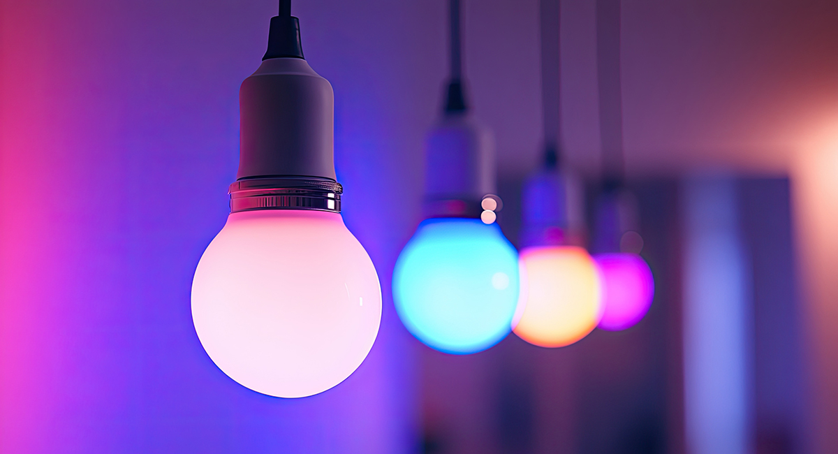
There are several ways to overcome this issue, to ensure that all lighting products at the end of the line deliver acceptable performance. Homogeneous placement refers to populating any given batch of boards using only LEDs from one reel. This ensures consistent luminosity across the complete light emitting surface of the lamp (figure 1). Because mixing LEDs from different reels on the same board could give unpredictable results, it is important to be sure that the reel contains enough LEDs to build a suitable number of boards and stop production when insufficient LEDs remain to complete the next board.


Figure 1: LEDs from the same BIN ensure consistent lighting and uniformity from unit to unit.
Alternatively the designer can correct for the differences in luminosity by placing a suitable resistance value in series to regulate the LED current. Choosing lower resistance values for lower-luminosity LEDs, and higher values for higher-luminosity parts (figure 2) can equalise the output of all parts. In this case, for any given BIN, the LED and calculated current-limiting resistor must be considered as a set. When a new reel is fitted, containing parts from a different BIN, the machine must recognise the new BIN and identify the feeder position that contains the correct accompanying resistance value.
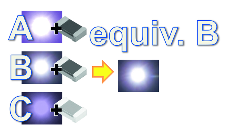
Figure 2: Correcting LED BIN by adjusting series resistance value.
Another approach is to create combinations of LEDs from different BINs, in pairs or small groups, ensuring all groups have identical total luminosity (figure 3). This allows the use of a single resistor value with each LED while at the same time ensuring uniform light quality within each lamp and from unit to unit.
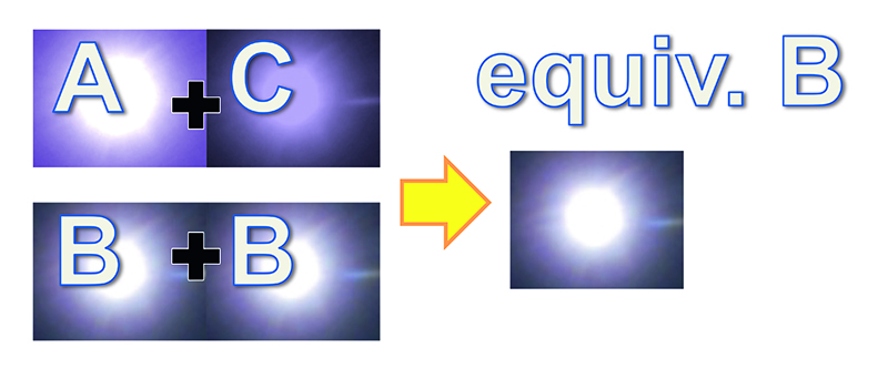
Figure 3: BIN compensation using combinations of LEDs.
Although any of these strategies can be effective, there is a complication: the numbers of available reels containing LEDs of any given BIN are subject to change over time as the factory inventory is consumed and replenished, and cannot be predicted. Hence if using homogeneous placement, the program cannot rely on the fact that another reel of the same BIN will be available when the current reel is exhausted. On the other hand, resistor-corrected or combination approaches must cater for a large number of alternative component pairings to cover any situation where LEDs of one or more BINs, are not available at any time.
Correcting for BIN in production
At the product design stage, software tools help engineers calculate the various combinations of LED BINs and resistors needed to ensure consistent luminosity. Understanding that a single LED part number can have as many as 250 or more BINs associated, a huge number of alternative files can be created to cover every possible combination.
Managing these files becomes a major challenge when it comes to generating assembly programs for placement machines in the SMT line, and subsequently running production continuously as component reels are exhausted and replenished. To prepare programs ahead of production, the programmer must be aware of the available inventory.
Moreover, in production, automating as much of the BIN-management process as possible is desirable to minimise opportunities for operator errors that can lead to mismatching of components and subsequent poor quality or failed units at end of line.
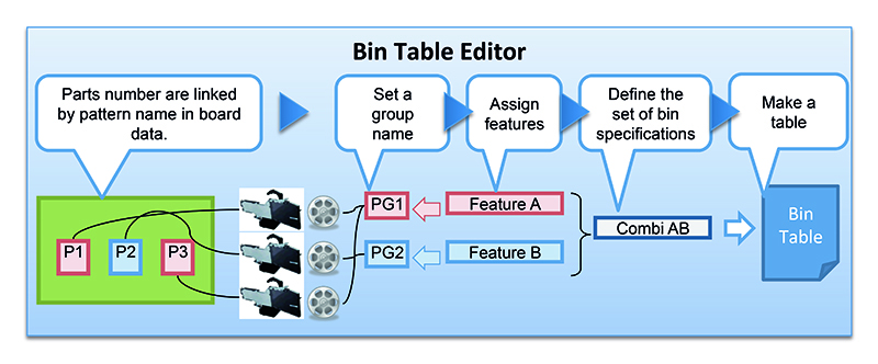
Figure 4: The BIN table editor enhances flexibility to handle unpredictable and changing inventory.
To overcome these challenges, Yamaha automated BIN-code management software contains a BIN table editor (figure 4). Using this tool, a technician can import pattern names contained in the board data, avoiding time-consuming and error-prone manual data entry. The BIN-code management software detects the part numbers at feeder stations and automatically selects the appropriate target parts to generate the BIN table. In addition, the software allows the flexibility to apply BIN specifications to the board program or to one more placement machines in the SMT line. It is therefore possible to populate LEDs and their associated resistors according to a production plan or use the BIN table as a sole reference to directly specify the BINs each machine must use.
In the first mode, Plan mode, the automatically generated BIN table is linked with the board data according to production lot. The operator can then control production simply selecting the lot name, without needing to examine BIN specifications.
The second mode, Machine mode, allows BINs to be selected directly and gives the flexibility to change BINs if necessary while a production lot is ongoing. In each case the software oversees production, allowing for replenishment by reel replacement or splicing, and is able to detect errors such as fitting an incorrect BIN that does not support the current program requirements.
Conclusion
The LED-lighting revolution presents a major opportunity for lighting brands and electronic manufacturers. However, unpredictability in BIN-code inventory complicates assembly-program generation. Time pressure and the potential for human error intensify the challenge. Fast and fool-proof automated tools are needed to help manage LED BIN codes on the factory floor.
The flexibility to accommodate all BIN-compensation strategies, including homogeneous placement, resistor correction, and array placement, lets manufacturers decide how best to maximise productivity and deliver high-quality LED lighting that meets the expectations of today’s demanding end users.