In a microprocessor-based system there will be several different clock signals used for the execution of instructions, movement of data to and from memory, and external communication interfaces.
A simple embedded controller may have a clock frequency of a few megahertz, while the microprocessor in a PC will typically expect a clock input of 15MHz. This will be multiplied internally to provide the clocks for the CPU and other subsystems. Other components in the systems may each have their own clock requirements. For example, a 25MHz clock for an Ethernet controller or 32.768kHz for a real-time clock (RTC).
A radio-frequency (RF) system requires an accurate frequency reference to enable end-to-end communication and allow unwanted signals and noise to be filtered out.
Oscillator characteristics
As well as the basic need to provide the specified frequency, an oscillator may have to meet other requirements, depending on your application.
For example, many applications require a very precisely defined frequency. This is particularly important for systems that need to communicate with other devices via serial or wireless interfaces.
The accuracy is typically measured in parts per million (ppm).
For handheld and battery powered equipment, low power consumption will be essential. This is particularly true for an RTC, as this part of the circuit will always be active, even in low-power or standby modes.
And, finally, you may need to consider factors such as the operating environment, cost and form factor.
Pitch perfect
Any oscillator uses a resonant or tuned circuit of some sort, together with amplification and feedback, to generate an output at a specific frequency.
The tuned circuit can be based on a resistance-capacitance (RC) or inductance-capacitance (LC) network. These are simple and allow the frequency to be varied over a wide range. However, designing an accurate RC or LC oscillator requires the use of expensive precision components. Even then, they cannot meet the highest levels of accuracy and stability required by many applications.
A crystal, typically quartz, can also be used as a resonant component. The crystal is cut with two parallel faces that have metal contacts deposited on them. Quartz exhibits the piezoelectric effect, which means that when the crystal is put under pressure a voltage is generated across the faces. Conversely, when a voltage is applied the crystal changes shape.
Feedback causes the crystal to oscillate at its natural resonant frequency. This is defined by the size of the crystal and how it is cut. The most common cut is called AT. This can be used for a wide range of frequencies and has good thermal stability.
A crystal resonator has a very high quality (Q) factor which means that the frequency is precisely defined and very stable, so crystals can be used as the basis of low-cost, high-accuracy oscillators.
The structure of a crystal resonator and the equivalent circuit is shown in Figure 1. The value Cp represents the capacitance of the two parallel electrodes. The components Ls, Rs and Cs represent the mechanical properties (mass, internal friction and elasticity) of the crystal.
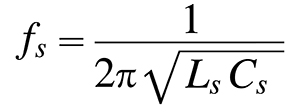
The equivalent circuit shows that there are two possible resonant frequencies: one due to the series connection of Ls and Cs, and the other from Cp in parallel with the inductance.
The series resonance is defined by:
The parallel resonant frequency is:
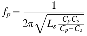
The two frequencies are typically less than one percent apart, and the oscillator circuit defines which of these resonant modes is used. Most oscillators use the parallel mode.
For high frequencies, above about 75MHz, the crystal can be made to oscillate at a multiple of the fundamental frequency, or overtone.
Oscillator circuits
The oscillator circuit is often integrated into the device that requires the clock signal. For example, many microcontrollers and similar devices have two pins where you can simply connect a crystal and a pair of ceramic capacitors to complete the circuit.
The total load capacitance (CL) of the circuit needs to match the specified CL of the crystal. This will be made up of the ceramic capacitors plus any stray capacitance from the crystal package, the oscillator input pins and the circuit board tracks.
It is not easy to accurately calculate all the stray and parasitic capacitances in the circuit, so you can start with an estimate (typically around 4 to 6pF) and then measure the output frequency to see if the value of the capacitors need to be adjusted.
If the total CL is larger than the specified CL, the oscillation frequency will be reduced. If the CL is too low, the frequency will be higher.
If the CL is too far out either way, the oscillator may not start up at all.
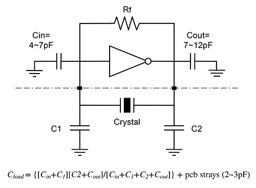
Above: Figure 2. Oscillator components and stray capacitance
You can also build an external oscillator circuit using a transistor or inverting logic gate as the feedback amplifier, as shown in Figure 3. However, designing a high-quality oscillator is challenging even though most crystal vendors will provide design guides, so it may be simpler to buy an off-the-shelf oscillator module. The oscillator module contains a crystal and all the components needed, including the load capacitors. This guarantees that you will get a high-performance oscillator at reasonable cost. All you need to do is provide a suitable power supply.
Crystal oscillator modules are good choices for applications that require accurate and stable frequencies, such as Ethernet interfaces or wireless communications systems.
Variations on a theme
The fact that the frequency varies with the external CL makes it possible to construct crystal oscillators where the output can be adjusted within a small range. This can be useful in RF applications where a receiver, for example, needs to adjust its own frequency to match the received signal.
A voltage-controlled crystal oscillator (VCXO) uses devices called varactors (or varicap diodes) as the load capacitors. The capacitance of the varactors changes with an applied control voltage which, in turn, alters the frequency of oscillation.
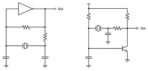
Above: Figure 3. Oscillator circuits
The key parameters of a VCXO are ‘pullability’, control voltage range and clock jitter.
- The pullability defines the frequency change for a given change in control voltage. A larger value means that the oscillator can operate over a larger range, but a smaller value means better stability and lower phase noise. The maximum tuning range is normally around +/-200ppm.
- The control voltage is usually from 0V to 2 or 3V.
- The clock jitter is higher than a fixed-frequency oscillator, particularly at the extremes of the tuning range where it is operating at its limits.
If you require greater stability over operating temperature range than a normal crystal oscillator can provide, you might need to use a temperature compensated crystal oscillator (TCXO). These are also available as off-the-shelf modules with a wide range of parameters.
A TCXO includes a circuit that measures the ambient temperature and then generates a control voltage to adjust the frequency of a VCXO to compensate for the effect of temperature changes.
The TCXO calculates the required control voltage from the temperature frequency response curve of the crystal.
A TCXO module often also includes its own voltage regulator so that the oscillator is not affected by variations in the external supply voltage.
Conclusions
A quartz crystal provides a highly accurate, stable and low-cost frequency reference.
Crystals and crystal oscillators are available with a wide range of parameters and implementations to meet the requirements of your application.
Many devices integrate the oscillator circuitry, making the design-in process very simple. As an alternative, particularly if a higher quality clock is required, you can use a crystal oscillator module.
These typically have higher accuracy and stability than integrated oscillators. Modules are also available with voltage controlled frequency or temperature compensation.


