


The Belt Starter Generator (BSG) or Integrated Starter Generator (ISG) is just one of the solutions in the EV development timeline. Combining the BSG/ISG with the ICE creates a Mild Hybrid Electric Vehicle (MHEV), and this hybrid power solution creates new opportunities for electronic modules and electric motors. The BSG/ISG unit replaces the starter and alternator functional modules, while augmenting the ICE functionality. In this architecture, there are two batteries, one traditional 12V battery and another 48V lithium-ion battery.
The 48V lithium-ion battery supplies higher power loads, such as the inverter that powers the electric motor of the BSG/ISG. The 12V battery remains on MHEVs to power legacy electronic control modules in the vehicle and provide alternate low voltage electronics power to 48V systems if needed. The MHEV gives automotive original equipment manufacturers (OEMs) an intermediate step between traditional combustion engine propulsion and fully electric propulsion found in Battery Electric Vehicles (BEV).
Tougher CO2 emissions legislations mean that automotive fleets must reduce vehicle CO2 output across the board. With a relatively low barrier to implementation, taking an existing vehicle platform and adding certain modifications will allow OEMs to provide MHEV variants to fleet offerings. The MHEV brings down the average CO2 output from a vehicle by providing functionality that reduces the amount of fuel used by the combustion engine. The BSG/ISG unit enables start-stop functionality, energy recovery when coasting or braking, energy generation when the ICE is running, as well as electric drive or boost depending on system implementation. When in energy recovery or energy generation modes, the BSG/ISG operates as a generator providing reverse power flow back to the 48V battery pack. In turn, a DCDC module converts 48V to 12V to charge the legacy 12V battery.
MHEVs are a ‘soft entry’ into the EV space because in many cases the car owner does not have any perceived difference in performance or functionality from a traditional ICE vehicle. MHEVs do not require any form of charging from the electrical grid, are refueled quickly and do not give the driver range anxiety on long trips as compared to some BEV variants. In fact, the only time a driver or passenger may notice the functional differences of a MHEV is when the ICE shuts down under specific driving scenarios. Engine temperature, time between the last engine shutoff, battery voltage levels and state of charge, electrical loads and minimum attained vehicle speed are some of the specific conditions monitored by an algorithm to determine usage of the ICE or BSG/ISG. The complexity behind these algorithmic decisions is not the subject of the article.
There are different locations in the vehicle for integrating a BSG/ISG. P0 – P4 are the current designated positions, and each provides varying levels of capability and design challenges for the system.
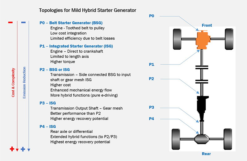
Above: Figure 1. Locations for BSG/ISG in vehicle powertrain
Power output, method of coupling to the powertrain and associated functions of the BSG/ISG are not identical for these locations. As discussed earlier, the functionality of the unit can include start-stop, electric drive at lower speeds, electric boost to the ICE and energy recovery. Energy recovery can occur during coasting or braking when the ICE is off, while energy generation (generator functionality) occurs when the ICE is running in order to provide power to the 48V lithium-ion battery. A quick overview of the locations will reveal that energy recovery is not possible in positions P0 or P1 when the engine is off. However, positions P2 – P4 can recover energy when the ICE is off during coasting or braking because the mechanical motion of the driveline will turn the electric motor to provide generator capabilities. The chart below calls out the functional variations based on the vehicle positions of P0 – P4.
BSG/ISG units have peak output power from 5kW up to 25+kW and the installation location and coupling mechanism will affect this rating. Belt drive systems will be limited in power due to belt slippage and maximum applied torque, whereas direct drive systems using gear mesh or a direct connection to the crankshaft can have higher power output. The installation positions of P0 – P4 affect not only peak power, but also system level efficiencies.
Location P0 peak power is limited by the belt linkage. Energy recovery or generation requires the ICE to be on in order to spin the e-machine. The rotation of the e-machine directly ties to the rotation, or revolutions, of the ICE. Therefore, if the ICE revolutions per minute (RPM) drops due to coasting or breaking, the power generated by the BSG for the 48V battery is lower as well. This limited energy recovery functionality means the engine shutdown algorithm will be less aggressive, and will not save as much fuel as other options.
Location P1 is a direct connection to the engine crankshaft and does not suffer from slippage related to a belt. Higher peak output power and torque is achievable as compared to P0. The remainder of the functionality for location P1 is identical to P0.
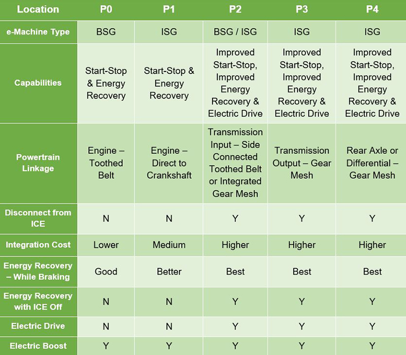
Location P2 is capable of belt or gear mesh linkages to the powertrain and is located between the ICE and the transmission input. A clutch system can engage or disengage the ICE from the driveline, which in this position allows for higher torque output and improved speed/torque ratio with the BSG / ISG. The clutch also allows for pure electric drive provided by the BSG / ISG at low speeds while the ICE is off. Energy recovery functionality is truly regenerative, as the e-machine has a connection to the driveline and will continue to spin even with the ICE off. This improved energy recovery functionality allows for a more aggressive engine shutdown algorithm, saving more fuel than positions P0 or P1.
Location P3 is a gear mesh linkage on the output shaft of the transmission. Losses from both the ICE and transmission are minimal as related to positions P0-P2. Similar to position P2 the clutch allows the ICE to disconnect from the driveline, allowing for electric drive at lower speeds as well as regenerative energy while coasting or breaking with the ICE off.
Location P4 is a gear mesh linkage on the rear axle or differential and has all the capabilities of position P3. This location, as well as P3, allows for maximum energy recovery. Installing an ISG at this position in a front wheel drive (FWD) vehicle will allow for all wheel drive (AWD) functionality with a properly sized lithium-ion battery.
It is possible to have more than one e-machine implemented in positions P0 – P4. Having a combination allows vehicle manufacturers to implement additional features or re-use more of the vehicle’s previous platform prior to converting it to a MHEV. Maximising re-use reduces the cost impact when transitioning to the MHEV topology, benefiting both the OEM and the customer.
End-users will notice subtle differences in a MHEV such as the ICE turning off at a stop or turning off the ICE while coasting or braking. They will notice that if their vehicle has a BSG / ISG unit in locations P2 – P4 the ICE may not immediately restart, as the electric drive will begin moving the vehicle from a full stop. MHEVs are not a zero-emission vehicle (ZEV) like BEVs, but they allow for a reduction in CO2 output, from 4% to 10% (Yole Développement, 2020), while OEMs upgrade their fleets with vehicle electrification technology. Small steps and giant leaps will create the cumulative effect required to move towards a cleaner environment. MHEVs will help reduce the environmental impact of transportation while meeting performance expectations of the consumer, until such time that BEVs can address all use cases.
These multi-function e-machines, which put the ‘hybrid’ in MHEV, contribute to one-third of all EVs produced yearly and will continue to be one-third of the yearly production volume through at least 2026. With a compound annual growth rate (CAGR) of 19.8%, these systems will grow in volume substantially while proliferating the EV fleet transition (Strategy Analytics, 2020).
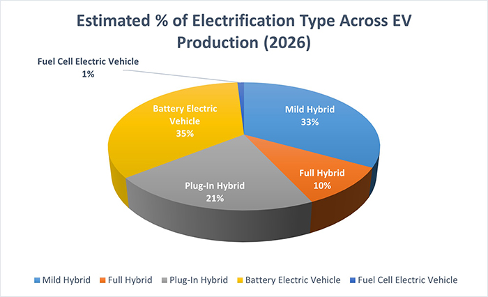
Above: Figure 2. Electrification classification for EVs in 2026
There are many engineering considerations for the design of a BSG / ISG unit. The module design is affected by peak and constant output power, location (P0 – P4), cooling method and space constraints. For the electronic control and the power electronics used in the inverter, the requirements of maximum power density, high efficiency and long-term reliability are all critical.
ON Semiconductor provides scalable technologies for automotive BSG/ISG designs. The portfolio includes medium voltage MOSFETs and automotive power modules, gate drivers, regulated power, and in-vehicle networking (IVN) solutions. Customers collaborating with ON Semiconductor can implement high-performance solutions and develop a full array of power tiers for their BSG and ISG applications.