


This article originally appeared in the October ’21 magazine issue of Electronic Specifier Design – see ES’s Magazine Archives for more featured publications.
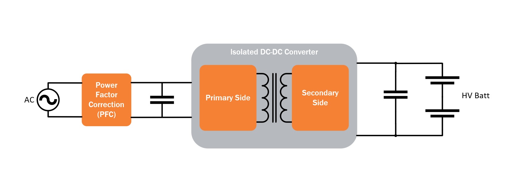 FIgure 1 – OBC power path functional blocks
Charging considerations with OBCs
OBCs are in battery electric vehicles (BEVs), plug-in hybrid electric vehicles (PHEVs), as well as (potentially) fuel cell electric vehicles (FCEVs). These three new energy vehicle (or NEV) types all have varying requirements when it comes to the system-level charging functions.
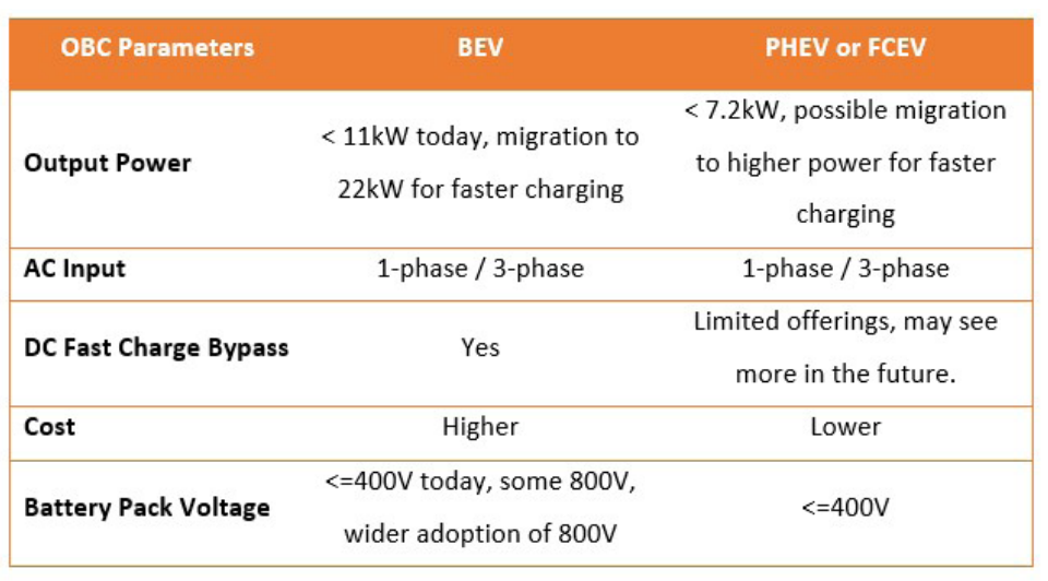
Table 1 | OBC system level requirements for BEVs, PHEVs, and FEVS
While an OBC converts AC power into DC power, it doesn’t need to when the incoming power is already DC: if the owner connects a DC fast charger to a vehicle, the OBC will be bypassed to allow the fast charger a direct path to the high-voltage battery.
The core function of taking AC input power and converting it to DC output power is to provide the proper voltage and current for charging the high-voltage battery pack. At a base level, this functionality is unidirectional, because it only allows power transfer from grid-to-vehicle. The process involves the given OBC unit varying the voltage and current based on the overall battery’s state of health and state of charge.
Design considerations of OBCs
The design constraints for OBCs are based on the following factors: the AC input, target output power level, battery pack voltage, cooling method, space constraints, and the question of whether the design is unidirectional or bidirectional for power flow.
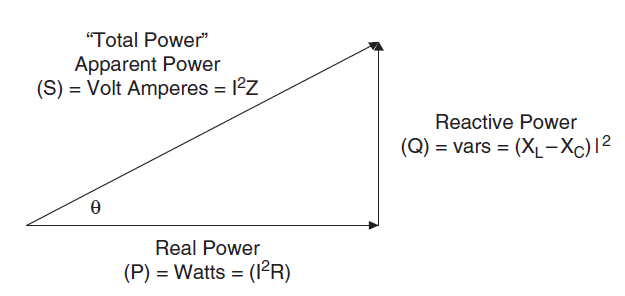
Figure 2 | Power triangle. Image from onsemi’s article: ‘Power Factor Correction (PFC) Basics’
Additionally, in many instances, these modules must support ASIL (Automotive Safety Integrity Level)) B or C for functional safety.
When considering the overall hardware functional blocks of an OBC, a designer should address the following:
• AC rectification and power factor correction (PFC) on the incoming AC source • Primary side DC-DC
• Secondary side rectification (passive or active)
• Secondary side DC-DC control (if the technology is bidirectional)
• Voltage, current and temperature diagnostics
• In-vehicle networking (or IVN) for communication and diagnostics
• Communication to the electric vehicle supply equipment
• Isolation between the AC source, 12V battery, and the high-voltage battery – a highly important safety requirement For this discussion, the focus will be on the former four points.
Power factor correction
AC rectification and PFC help to minimise reactive power while maximising real power transfer and operating in AC to DC conversion mode. Without PFC in high-power systems such as OBCs, the power transfer will be rendered inefficient and the system’s thermal loading will increase accordingly. This block has the most variants when it comes to OBC design, as there are many implementations based on AC source input, output power, efficiency, and cost targets.
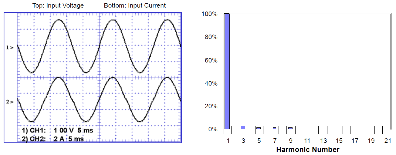
Figure 3 | Example low-power circuit using PFC Images from onsemi’s ‘Power Factor Correction (PFC) Handbook’
It is very common for the power factor (PF) in OBCs to have a specification of PF that is greater than or equal to 0.90 across the operating range, and more or equal to 0.98 in the typical operating range. A high PF maximises charging capabilities while also minimising line/grid currents and apparent power demand. In the future, there will be an enhanced focus on more improvements related to line/grid harmonic content, as well as improved modes for light loading conditions.
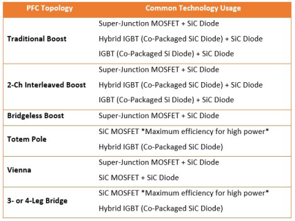 Table 2 | PFC typical device technologies
The PFC controller in the OBC performs multiple functions:
• It aligns the input phase current with the input phase voltage
• Reduces the peak current drawn from the AC source
• Minimises line/grid current total harmonic distortion (or THD)
• Ensures that the input current is as close as possible to a sinusoidal (having the form of a sine curve) waveform
Figure 4 shows that both the voltage and current are sinusoidal, and in phase. This minimises the reactive power component, thermal loading, and harmonics, allowing the maximum amount of real power to transfer.
While it is possible to use passive PFC in general applications, the practical implementation in OBC requires active PFC due to the higher power levels, space constraints, thermal requirements, and power factor targets imposed upon these systems.
Examples of common active PFC solutions for OBC technologies include traditional boost, bridgeless boost, totem pole, and a Vienna rectifier.
As the output power of the OBC increases, it is beneficial to use PFC topologies that reduce the number of diodes in the power path, or to use SiC (silicon carbide) Schottky diodes that have virtually no reverse recovery characteristics. Designers can also transition to SiC MOSFETs, which allows the PFC stage to switch at higher frequencies while handling higher system voltages – therefore increasing efficiency and energy density.
The next block in the power path is the primary side DC-DC converter. This circuit converts the high voltage DC link from the PFC into the appropriate voltage for charging. The output voltage and current will vary based on the state of the battery pack. A typical implementation for this DC-DC in a unidirectional design is LLC, but another possibility is to use PSFB (Phase Shifted Full Bridge).
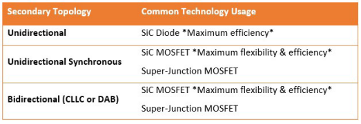 Table 3 | Secondary side device selections
For bidirectional designs, the implementations are CLLC or dual active bridge (DAB), and users should expect to see more solutions using these architectures as bidirectional capability expands. SiC MOSFETs are ideal in this situation as they allow for higher voltages and lower switching losses.
On the secondary side there can be passive rectification using diodes, synchronous rectification using power switches, a full bridge design supporting CLLC (bidirectional), or the second half of a dual active bridge (bidirectional). Passive rectification requires no control, but only allows for unidirectional grid-to-vehicle power flow. For higher efficiencies or 800V battery packs, SiC diodes provide the best solution in this situation.
Synchronous rectification is possible using super-junction MOSFETs or SiC MOSFETs in unidirectional designs, but in many instances such technology is considered expensive compared to a diode solution. For bidirectional capabilities, designs will use full bridge or a multi-leg half bridge solution. Based on the system power levels, voltages and efficiency targets, either Super-Junction MOSFETs or SiC MOSFETs will be used. SiC MOSFETs will provide higher efficiencies across all options and more easily address 800V systems, while Super-Junction MOSFETs can address cost-optimised 400V systems.
The output power ratings for OBCs tend to correlate to the size of the battery packs used in the vehicle. OBCs target higher output powers for larger batteries in BEVs, while lower output powers are targeted for smaller batteries in PHEVs. This balance prevents over-engineering the systems and helps to optimise charging times and cost.
BEVs have a wide range of options when it comes to the kilowatt-hour, or kWh, rating of the battery pack. The vehicle’s physical size, cost targets, and expected capabilities (such as range) influence this capacity. For instance, according to the Electric Vehicle Database, 2021, it is possible to have light passenger vehicles across multiple vehicle segments with battery pack capacities from 30kWh to 105kWh. And as for light passenger vehicles (which fall into larger SUV segments), research in Ford Motor Company, 2021 states that it will become more common for battery pack capacities to reach a high end of 110kWh to 150kWh or more.
Battery packs are increasing in kWh ratings to provide more range or address new automotive segments, while also (to expedite the charging process) adopting 800V more broadly in the industry.
Battery pack considerations for PHEVs, FCEVs, and BEVs
PHEVs and FCEVs have battery packs that range from 5kWh up to 25kWh. The capacities are much lower than the average BEV, as PHEVs rely on an additional source for power beyond the battery pack (PHEVs use an internal combustion engine, or ICE; and FCEVs use a hydrogen fuel cell).
When the battery pack drops below a certain level, or other conditions require it, the ICE or fuel cell can provide power to drive a generator that will charge the battery. For short ranges, this class of EV is capable of full electric drive, but it does not have nearly the electric range of a BEV. Nevertheless, more EVs in this class will, over time, migrate to 15+kWh battery capacities to increase the pure electric range.
BEVs have much larger battery capacities than PHEVs, and this affects OBC design and selection, as well as vehicle charge times. Consider a scenario where two different vehicles (a BEV and a PHEV) charge with the same version of an OBC and are plugged into the same capability electric vehicle supply equipment. If the BEV has a battery capacity that is four times the size of the PHEV, the BEV will take roughly four times as long to charge. (While this simplified view ignores the complexities of charging algorithms, it is a good enough estimate for this discussion.)
If both battery packs are depleted, then the BEV will take longer to charge. Charging time is a major consideration for both OEMs and customers, and it is of course a major factor in end-user satisfaction.
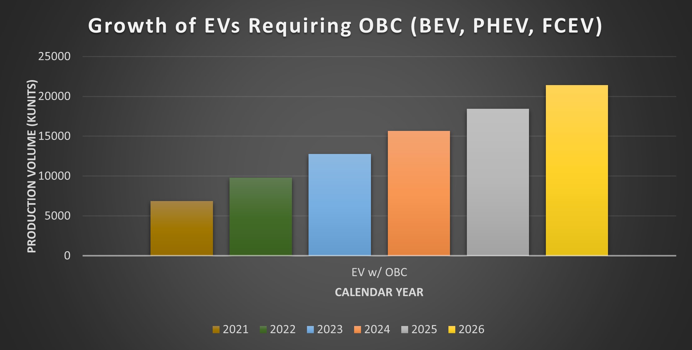
Table 3 | Secondary side device selections
Options to help with charge time improvements involve increasing the following: the power output of the OBC, the OBC efficiency, and the system voltage for the battery pack and associated OBC. All of these can help to reduce the charging time, which will therefore improve the overall user experience.
OBCs are seeing a rapid shift in architecture and power levels. As EV adoption rates continue to grow (see Figure 6), the need for highly flexible OBC designs is now more important than ever.
A recap of key OBC facts
• Energy density is increasing for EV battery packs
• Consumers want faster charge times
• OBCs are migrating towards higher power levels
• OBCs must address the benefits of 400V battery systems, as well as the wider adoption of 800V
• To increase end-user functionality, there is a shift to provide optional bidirectional capability in OBCs, allowing both grid-to-vehicle and vehicle-to-grid power transfer
• Owners will especially benefit from such functionality, as they can use their EV to power their homes in the event of a power outage – or work with utility companies to provide power back to the infrastructure grid
Closing points on OBC technology
In a drive to reduce charging times even further, we will start to see increased power output OBC modules in vehicles with smaller kWh energy density battery packs. Another possibility is to add support for DC fast charging to help PHEVs fully recharge in minutes. And as for larger battery packs, such as those used in BEVs, the trend will be to move to 11kW and 22kW OBC while continuing to support fast chargers and higher voltages.
For the power electronics used in the inverter, the requirements of maximum power density, high efficiency, supply chain stability, and long-term reliability are all critical. Accordingly, onsemi provides scalable technologies for automotive OBC power stages from 3.3kW to 22kW – and battery voltages of up to 800.