


Hence, they are becoming increasingly popular in automotive applications, including anti-lock braking systems (ABS), power steering, and electric and hybrid vehicles. However, in the space-constrained automobile environment, cooling is not always possible and higher temperatures may negatively impact the performance of nearby components. Designers of automotive subsystems constantly look for opportunities to reduce the amount of power dissipated as heat in BLDC motor applications, and careful design of the controller board achieves further efficiency gains. This article, by Pablo Mateos, Junior Automotive Applications Engineer, Diodes Incorporated, quickly reviews the structure and operation of a BLDC motor, discusses different methods of commutation used to control speed and position, and then presents the results of thermal measurements performed on two control boards designed to address the heat problems in automotive applications.
BLDC motor types
A BLDC has two main components – a rotor and a stator. Unlike in brushed DC motors where coils are attached to the rotor, a BLDC motor has the coil windings fixed to the stator. Wires are wrapped around laminated steel arms, forming stator coils. The rotor includes a permanent magnet with alternating magnetic poles, which rotates around a shaft. Single-phase and three-phase motors are the two most commonly used types of BLDC motor (the number of stator windings determines the number of phases). However, a single-phase motor can only turn in one direction; its simple structure consisting of a stator coil wound around four stator arms to create two pairs of electromagnetic poles when the coil is energised. Three-phase motors have three star-connected coils in the stator, allowing them to turn clockwise and counter-clockwise. They are typically larger and more expensive than single-phase motors but are easier to control and run smoother. Pole pairs in a BLDC motor can refer to the stator’s electromagnetic poles or the rotor’s magnetic poles.
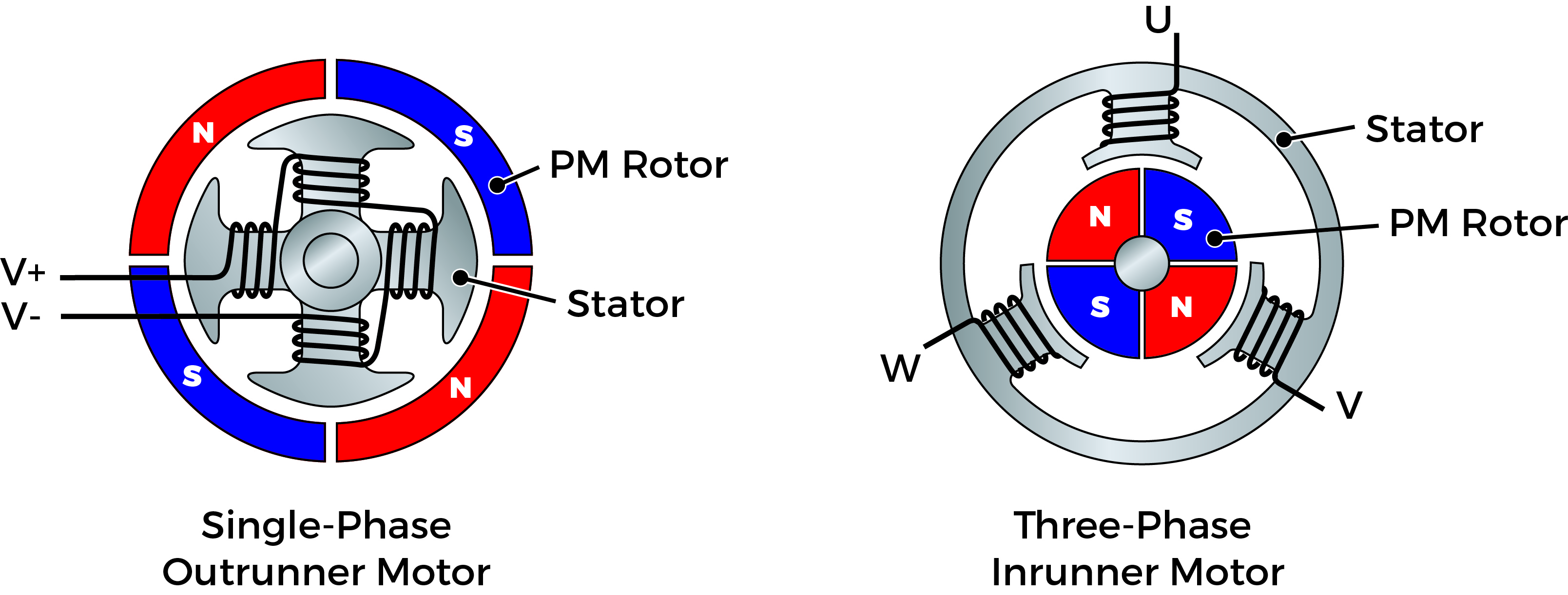
Figure 1. Structure of a single (left) and three-phase (right) BLDC motor
The simplest three-phase BLDC motor has three-pole pairs on the stator, with two or more poles on the rotor (depending on the application). The pole count affects motor performance; more poles causes more switching cycles during a single revolution because a 90° angle produces maximum torque between the magnetic fields of the rotor and stator. Therefore, increasing the number of poles improves torque but reduces the motor’s maximum rotational speed. Since there is no contact between the rotor and the stator (as in brushed motors), BLDC motors do not suffer from wear and tear, meaning extended periods without maintenance and a longer working life. They are also easier to cool because heat dissipates in the stator (not the rotor). These advantages make BLDC motors more reliable; an essential requirement for motors used in automobile applications.
BLDC motor commutation
The coils in a BLDC motor are static, so mechanical commutation (like that used in brushed motors) is not required. Instead, commutation is performed electronically using a microcontroller and six semiconductor transistor switches (Figure 2).
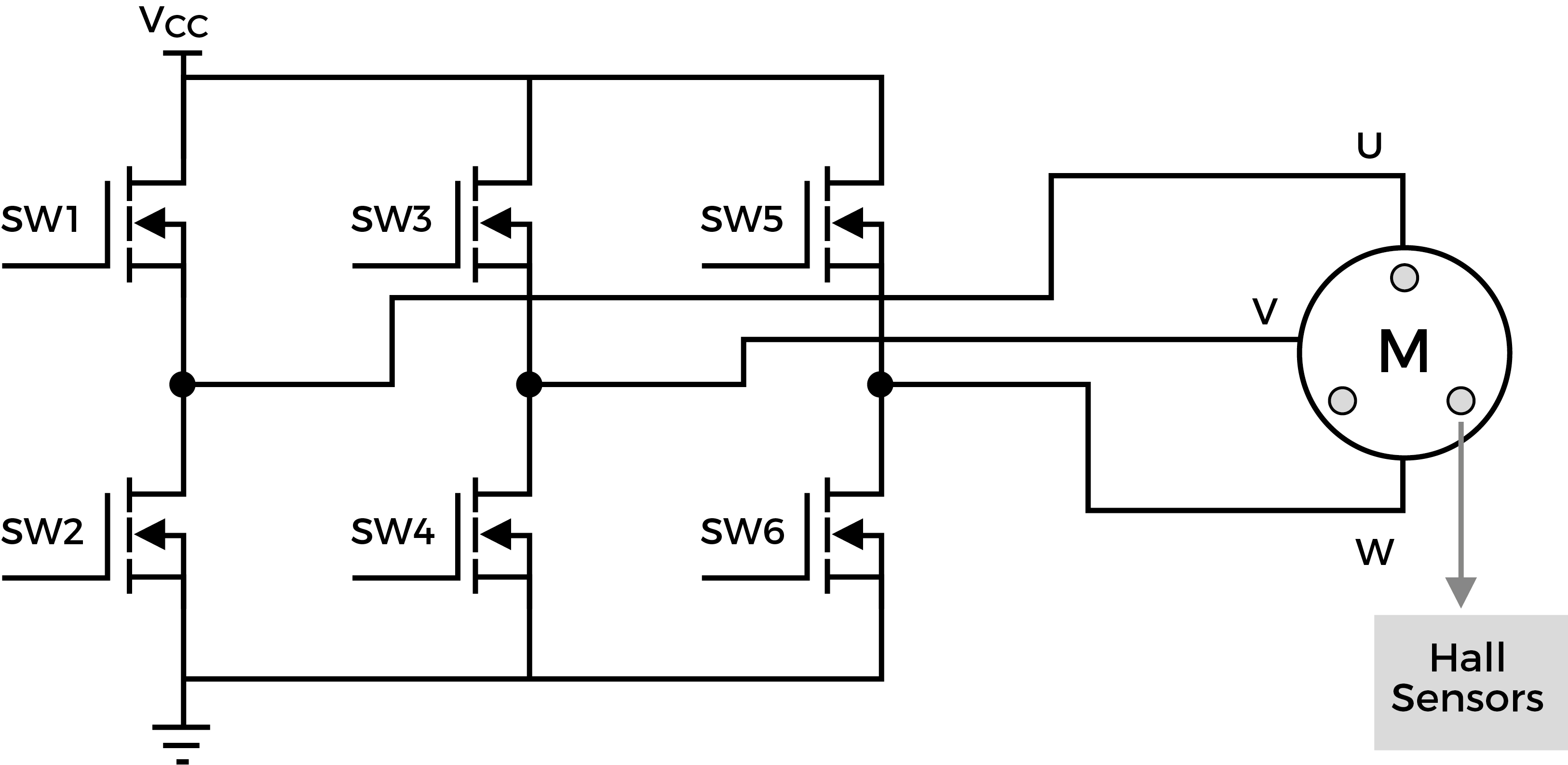
Figure 2. Three-phase BLDC Bridge Configuration
Electronic commutation requires a sequence of steps in which current from an external motor driver circuitry is delivered to each phase coil in a controlled sequence. The magnetic interaction between the magnet on the rotor and the energised stator coils produces the desired rotation. In a three-phase motor, current flows into one coil through a common node and continues through one of the others, leaving the third coil inactive. This way, it is de-energised just as the rotor pole is about to align with its electromagnetic counter-pole on the stator. The next phase is then energised, allowing rotation to continue. So that coils are energised at the correct time, it is critical to know where the rotor is located with respect to the stator. This is referred to as position feedback and can be performed using current sense resistors or, more commonly, magnetic Hall-effect sensors; three of which are placed at appropriate locations on the stator (inside the motor), each separated by 120°. When the pole is in position, these devices produce a digital signal (‘0’ or ‘1’) with multiple binary combinations corresponding to different rotor locations (Figure 3). Providing these binary codes to a microcontroller enables it to switch the six MOSFETs in the correct sequence.
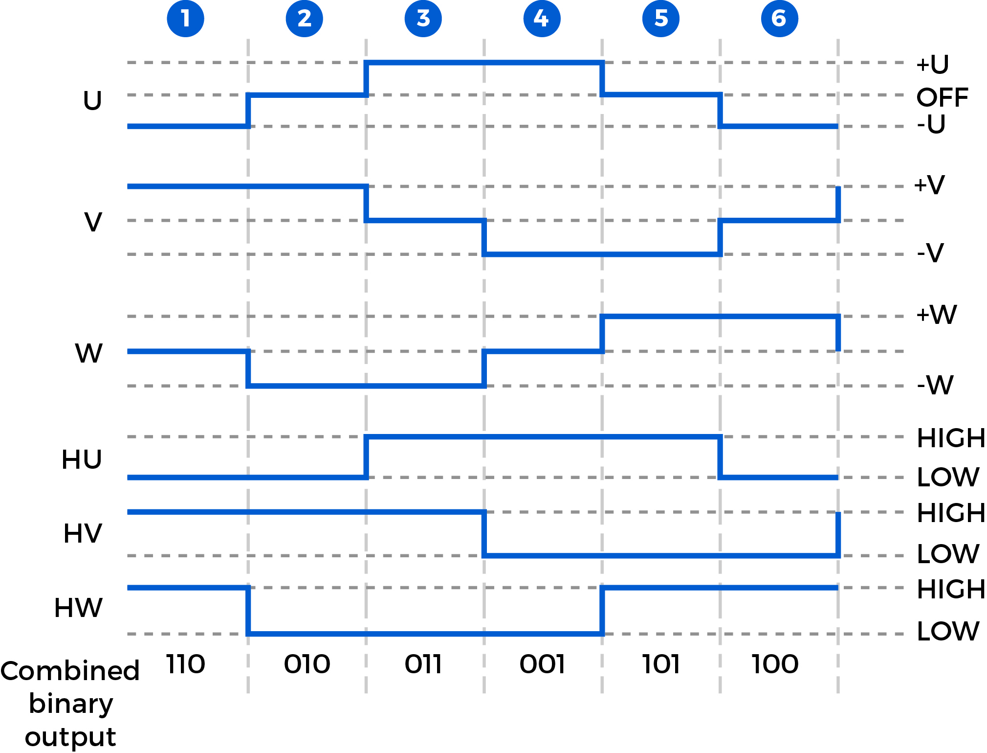
Figure 3. Binary pattern produced using Hall effect sensors to commutate a BLDC
MOSFETs are typically used as commutation switches. Alongside their gate drivers, MOSFETs can be a source of heat dissipated on the motor controller board. It is important to use devices that exhibit good thermal performance and to understand the amount of heat produced by measuring the temperature of the board when in operation. By providing this information to designers of automotive subsystems, they can design appropriate equipment enclosures.
Measuring thermal performance of motor controllers
To address the problem of heat dissipation, Diodes Incorporated has developed two demonstration, BLDC motor controller, printed circuit boards (PCB), which includes six of its DMTH6010LPDQ dual MOSFETs (AEC-101 qualified) and DGD05473FNQ gate driver ICs (AEC-Q100 qualified). The DDB094R2 demo board has one current sense resistor used for safety monitoring, and three Hall-effect sensors for commutation. To evaluate the thermal behavior of the boards, a thermal camera measured the surface temperature of the switching MOSFETs and the heat dissipated in the PCB at room temperature (25°C). The DDB094R2 was connected to a 77W (input power) BLDC motor (24V, 3.2A), and as the surfaces of the MOSFETs reached 75°C, there was a considerable margin to the maximum allowable operating temperature of 150°C (Figure 4).
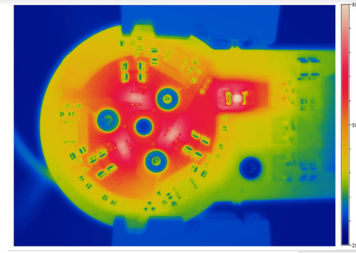
Figure 4. Thermal image of the DDB094R2 motor controller demo board driving a 77W BLDC
The DDB099 demo board includes three current sense resistors (one per phase) and three Hall-effect sensors to perform commutation using either approach. Due to its larger surface area, it was expected that the thermal performance of this board would be even better. When tested under the same conditions using the same conditions as those used previously, the temperature at the surfaces of the MOSFETs measured only 33°C, which is a considerable distance from the maximum allowable 175°C. Increasing the input power to 120W (24V, 5A), the surface temperature of the MOSFET only further rose to 40°C (Figure 5).
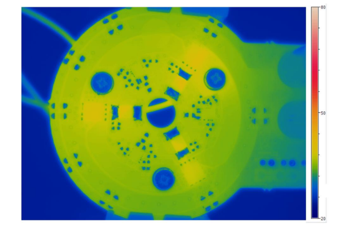
Figure 5. Thermal image of the DDB099 motor controller demo board driving a 77W BLDC
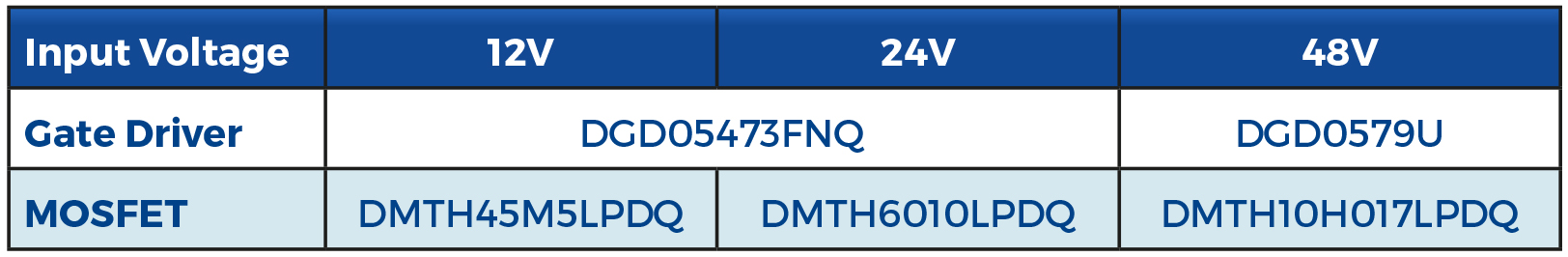
The DDB099 can be optimised for different voltage applications by using the components as follows:
Conclusion
BLDC motors are becoming increasingly popular in automotive applications because of their reliability and controllability. While they are more efficient than brushed motors, efficiency gains can still be made in the BLDC motor controller circuitry to further reduce the amount of power lost as heat. This article has explained the thermal performance of BLDC motor controllers, of which use various switching and automotive-compliant MOSFETs and gate driver ICs by Diodes Incorporated.