


LiDAR performance relies significantly upon the front-end transimpedance amplifier (TIA), which quickly recovers an avalanche photodiode (APD) signal to provide digital feedback. By comparing the time stamp of the feedback signal to the transmitted signal time stamp, the time-of-flight (ToF) can be calculated for ranging.
This article will briefly discuss the issues associated with developing the feedback circuitry performance for precise object detection using LiDAR. It will then introduce an Analog Devices TIA. It will show how to take advantage of its high speed, bandwidth, and low input impedance for quick recovery from reflected light which can produce nanosecond (ns) photodiode rise time. To achieve the best overall performance, it will also show how to reject the APD dark current and ambient light through AC coupling to allow accurate ToF estimations.
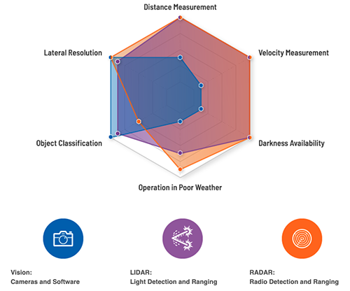
Above: Figure 1. Vision (cameras and related software), radar, and LiDAR systems complement each other to inform an ADAS so it can take appropriate action. (Image source: Analog Devices)
Key elements of ADAS
At the heart of ADAS are sophisticated sensing systems to analyse external objects. The identification and location of these objects enable a vehicle to either notify the driver or take the appropriate action – or both – to avoid incidents. The sensor technologies behind ADAS can include an image camera, inertial measurement units (IMUs), radar, and of course, LiDAR. Of these, LiDAR is a critical optical technology that performs autonomous vehicle poor weather and lateral distance sensing and ranging. It forms an integral part of an ADAS system (Figure 1).
An ADAS system uses cameras to detect and recognise external objects such as vehicles, pedestrians, obstacles, traffic signs, and lane lines quickly and accurately. The analysis triggers the appropriate response to maximise safety. Responses include lane departure warning, automatic emergency braking, blind-spot alerts, and driver awake and alert monitoring, among others. The camera’s strengths are object classification and lateral resolution.
The self-contained IMU system measures angular and linear motion, usually with a triad of gyroscopes, magnetometers, and accelerometers. An IMU is gimballed to reliably output integrated angular velocity and acceleration quantities. A gimbal is a pivoted support that allows the rotation of an object about a single axis. A set of three gimbals, one mounted on the other with orthogonal pivot axes, allows an object mounted on the innermost gimbal to remain independent of the rotation of its support. The IMU improves the GNSS accuracy from meters (m) to centimetres (cm) for accurate lane positioning.
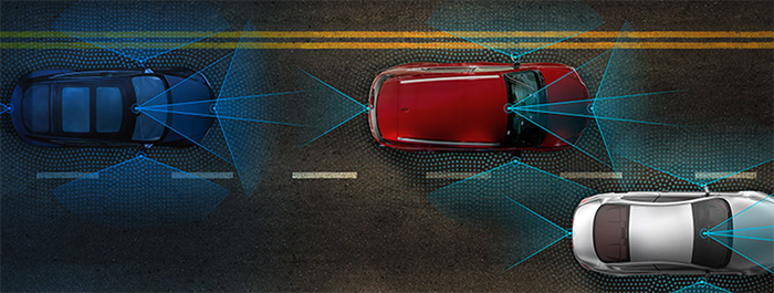
Above: Figure 2. Cameras, radar, and LiDAR together provide a 360° field of vision around vehicles to ensure the safety of those both inside and outside. (Image source: Analog Devices)
Automotive radar technology adaptations measure many different variables, including distance and velocity, while also providing ‘visibility’ in darkness. Typically, 24 and 77 gigahertz (GHz) signal rates are used for high resolution. The radar sensor captures reflected signals off different objects within its field of view. The vehicle then analysers the sensor output within the context of all the other sensor inputs to determine if adjustments in steering and braking are required to, for example, prevent collisions.
To complete the ADAS picture, LiDAR utilises optics with a spectral response range of between 200 and 1,150 nanometres (nm). The system measures the ToF from laser transmit to reception of reflected signals. The compilation of many signals enables the creation of accurate multidimensional depth maps of the vehicle’s surroundings. Applications for LiDAR include collision avoidance, blindside detection, emergency braking, adaptive cruise control, dynamic suspension control, and parking assist. LiDAR systems surpass radar in terms of lateral resolution and capabilities under poor weather conditions.
ADAS and autonomous vehicles require multiples of these sensors placed around the vehicle for 360 degree detection and analysis (Figure 2).
As these sensors and their associated software improve, drivers, passengers, and anyone proximal to the vehicle will become safer.
LiDAR optics
LiDAR designs have progressed from ‘coffee can’ sensors rotating on the car roof and valued at approximately USD $75,000, to more modern approaches costing in the range of $1,000 each. The cost reduction is primarily attributable to advances in lasers and associated electronics. The move toward semiconductor-only lasers (vs. rotating coffee can) and the associated scaling in semiconductor processes are the main reasons cost and size have been reduced. Now, multiple LiDAR sensors can be placed across the vehicle’s front and back, as well as on the sides, for low-cost 360 degree visibility.
A typical LiDAR design can be broken down into three main sections: data acquisition (DAQ), analogue front-end (AFE), and laser source.
The DAQ contains a high-speed analogue-to-digital converter (ADC) and the corresponding power and clocking to collect the ToF data from the laser and the AFE. The AFE contains the APD light sensor and TIA to capture the reflected signal. The entire signal chain conditions the APD output signal, which feeds into the ADC in the DAQ section. The AFE also includes the delay timing in its output to the DAQ. The laser portion contains the lasers and associated drive circuitry and transmits the initial laser output signal.
The LiDAR AFE
As shown in Figure 3, an example LiDAR receiver signal chain starts with a high voltage reverse bias (-120 to -300V), low input capacitance APD followed by a TIA, such as Analog Devices’ LTC6561HUF#PBF. It is important to design for lower APD input and PC board parasitic capacitances to complement the TIA’s high-speed 220MHz gain-bandwidth product (GBWP). The TIA input section requires additional attention to achieve the desired level of signal integrity and channel isolation so that there is no additional noise added to the current signal generated by the APD, thus maximising the SNR and the object detection rate of the system.
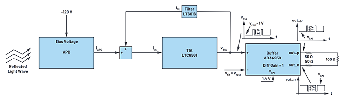
Above: Figure 3. An AFE for this design comprises the APD, the LTC6561 TIA, and the ADA4950 differential in/out high-speed amplifier. The LT6016 is an amplifier filter that dampens high-speed signal ringing. (Image source: Analog Devices)
To enhance the signal integrity, the TIA has a low-pass amplifier filter, Analog Devices’ LT6016, that dampens high-speed signal ringing. The TIA converts the APD output current (IAPD) to an output voltage, VTIA. The voltage VTIA transmits to the differential buffer amplifier (Analog Devices’ ADA4950-1YCPZ-R7) that drives the input of the ADC (not shown).
To compute distance using the ToF, the increment of the ADC sampling rate is used to determine the resolution of the received light pulse, Equation 1:
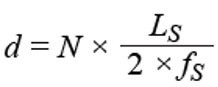
Where:
LS = Speed of light (3 x 10⁸m/second (m/s))
fS = ADC sample rate
N = Number of ADC samples in the time interval between when a light pulse is generated and when its reflection is received
For example, if the ADC’s sample rate is 1GHz, each sample corresponds to a distance of 15cm.
There must be near zero sampling uncertainties since even a few samples of uncertainty results in considerable measurement errors. Consequently, LiDAR systems use parallel TIAs and ADCs to drive towards zero sampling uncertainty. This increase in channels increases power dissipation and PC board size. These critical design constraints also require high-speed, serial output ADCs with JESD204B interfaces to solve parallel ADC issues.
LiDAR sensors
As mentioned, the key sensing element in a LiDAR system is the APD. The reverse voltage bias of these photodiodes, with internal gain, ranges from tens of volts to hundreds of volts. The APD signal-to-noise ratio (SNR) is higher than a PIN photodiode. Additionally, the APD’s fast time response, low dark current, and high sensitivity set them apart. The APD spectral response range is within 200 to 1,150nm to match the typical spectral range for LiDAR.
A good example of an APD is Marktech Optoelectronics’ MTAPD-07-010 with a spectral response ranging from 400 to 1,100nm, peaking at 905nm (Figure 5). The device’s active area measures 0.04mm square (mm2). It dissipates 1 milliwatt (mW), has a forward current of 1 milliampere (mA), and an operating voltage of 0.95 x its breakdown voltage (Vbr) of 200V (max). Its rise time is 0.6ns.
The typical semiconductor-based APD operates with a relatively high reverse voltage in the tens or even hundreds of volts, sometimes just below breakdown (per the MTAPD-07-010 at 0.95Vbr). In this configuration, absorbed photons excite electrons and holes in the strong internal electric field to generate secondary carriers. Across a few micrometres, the avalanche process effectively amplifies the photocurrent.
As a result of their operating characteristics, APDs require less electronic signal amplification and are less susceptible to electronic noise, making them useful with extremely sensitive detectors. Silicon APD’s multiplication, or gain factor, varies depending upon the device and applied reverse voltage. The MTAPD-07-010 has a gain of 100.
TIA solutions
In operation, the LiDAR emits a digital burst optical signal, the reflections of which would be captured by the MTAPD-07-010 APD. This requires a TIA with fast saturation overload recovery time, and fast output multiplexing. The LTC6561 low-noise, four-channel TIA with a bandwidth of 220 megahertz (MHz) meets these requirements (Figure 4).
In Figure 4, reflected laser signals (per Figure 3) are captured by the APD array and the four low noise, 200MHz TIAs. The TIAs quickly transmit the captured signals to the ToF detector. The 1 nanofarad (nF) capacitors on the input of the four TIAs effectively filter and eliminate the APD dark current and ambient light conditions, preserving the TIAs’ dynamic range. However, the value of the capacitors affects switching times, so designers need to factor that into their design.
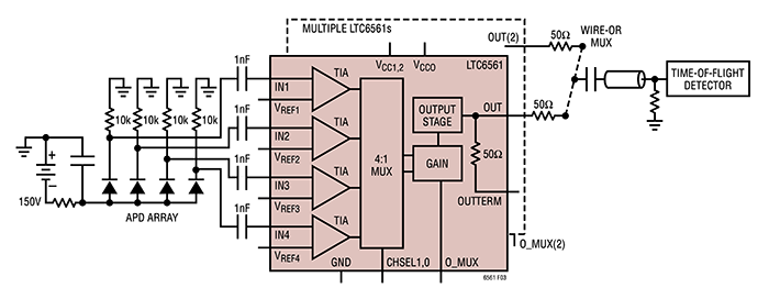
Above: Figure 4. The LTC6561 quad TIA with independent amplifiers and a single multiplexed output stage was designed for LiDAR utiliSing APDs. (Image source: Analog Devices)
Under intense optical illumination, APDs can conduct large currents, often more than 1 ampere (A). The LTC6561 survives and quickly recovers from large overload currents of this magnitude. Rapid overload recovery is critical for LiDAR applications. Fast 1mA overload recovery takes 10ns to settle (Figure 5).
In Figure 5, as the level of input current exceeds the linear range, the output pulse width widens. However, the recovery time remains in the 10s of ns. The LTC6561 recovers from 1mA saturation events in less than 12ns without phase reversal, thereby minimising data loss.
Conclusion
The path to successful autonomous vehicles starts with the integration and fusion of cameras, IMUs, radar, and LiDAR. LiDAR, in particular, holds promise when the issues associated with achieving precise object detection using this optical technology are understood and adequately addressed.
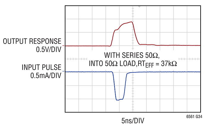
Above: Figure 5: The LTC6561 survives and quickly recovers in 10ns from large overload currents of 1mA. (Image source: Analog Devices)