
Buttons and switches addressing design needs
Touchscreens and membrane switches are useful for visual and low-profile control panels. However, some applications require designers to emphasise safety, ease of access, the switching of high voltages or current, a known configuration at power up, or robustness. For such situations, mechanical switches and buttons are often ideal, but designers need to choose carefully. Rich Miron, Applications Engineer at Digi-Key Electronics, explains.
There are numerous types of mechanical switches with variances in shape, style, size, function, power capabilities, and mechanical behaviour. This article will help designers sort through the selection parameters and how to best apply some of the latest devices.
Which switch or button?
To decide which switch is appropriate, first determine the requirements for the system. To find a mechanical switch for an application, first find the switch form factor that fits the ergonomic and physical needs, then choose a switch with the appropriate electrical and environmental specifications that fits the form factor.
Image above: Figure 1. The RAFI USA Lumotast 16 emergency stop button is simple to install and easily fits into a standard 16.2mm mounting hole. (Image source: RAFI)
Emergency stop
An obvious example of safety is the emergency stop button. Many industrial systems absolutely must have a big red or orange button with the words ‘Emergency Stop’ in large, reader friendly letters. This button must be in an obvious and easily reachable position, must be easy to depress, and there must be clear tactile feedback to indicate the switching function has been completed. Failure to meet this criteria can be hazardous in some industrial environments.
An excellent solution for this application is the Lumotast 16 Emergency Stop pushbutton from RAFI USA. This NO (normally open) button has the familiar big, conical mushroom shaped button (Figure 1). When an operator slams their hand down on this button, the two silver contacts connect, latch, and remain in contact even when the operator’s hand is removed. To reset the button to the open position, the mushroom head is rotated in either direction.
The Lumotast 16 can handle up to 6A and 250W, and is designed for high reliability operation. The interior switch design has three redundant contacts in parallel, so if one set of contacts fails to connect, the other two ensure a reliable stop event. To provide visual confirmation of a connection, the switch is wired to illuminate bright red when activated. The front side is rated at IP67, making it suitable for most harsh industrial environments.
With a 30mm button diameter, the Lumotast 16 is big enough to be used in industrial control panels, and is still small enough to be implemented in handheld control boxes.
To install the Lumotast 16, first make sure there is a mounting depth clearance of 18mm under where the switch will be located. Drill a 16.2mm mounting hole. Place the yellow mounting hole collar with ‘Emergency Stop’ in black letters on top of the mounting hole. Then place the Lumotast 16 switch into the mounting hole and secure it using the included mounting ring nut. Wire connections are made to the two standard male quick connect spade terminals on the underside.
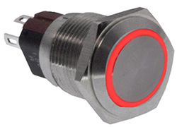
Above: Figure 2. The E-Switch PVA3 with a red illuminated bezel. It is mounted almost flush to the panel, making it more resistant to vandalism than switches with higher profiles. (Image source: E-Switch)
Resistance to vandalism
Another important application for mechanical pushbuttons is protection from vandalism. Anti-vandal switches need to withstand deliberate attempts to breach the switch construction, such as repeated blows from a hammer or attempts to pry the switch free.
For anti-vandal applications, E-Switch makes the PVA3H2B0SS3R1 SPDT vandal resistant illuminated pushbutton switch. This is a 2A, 36V DC switch rated to IP65. It has an RGB illumination ring, and its low profile makes it more resistant to vandalism (Figure 2).
This switch mounts almost flush to any panel with a 16mm hole. Make sure that the installation position has enough clearance to connect to the contacts underneath. This is an SPDT switch with four contacts, with an additional three LED contacts for RGB illumination with a common ground. This makes for a total of eight connections that need to be made beneath the panel. Plan the panel layout so that all the connections can be easily made without cramping or bending the connecting wires.
The mounting panel can be from 1-8mm thick. However, thicker panels provide more robust protection against vandalism.
Select the appropriate PVA3 configuration for the application, either momentary contact or latching contact. Activate the switch by pressing the actuator into the body of the switch. A flat actuator flush with the switch shoulder indicates the button is active, a high actuator indicates the button is inactive.
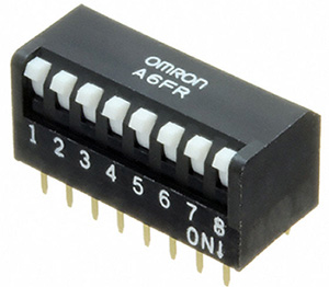
Above: Figure 3. The Omron A6FR series of DIP switches with short actuators, also called piano switches, are through-hole mounted into a socket or PC board. (Image source: Omron)
To provide visual feedback of the switch condition, use microcontroller or programmable logic controller (PLC) signals to illuminate the red, green, and blue LEDs in the indicator ring. To generate custom colours, connect the LEDs to pulse width modulated outputs from a microcontroller or PLC.
For additional resistance to vandalism, the switch comes in a choice of nickel or stainless steel for the switch body and actuator.
Reading configuration
Sometimes switches aren’t needed for user control, but instead for development or configuration behind the scenes. While EEPROM or flash can provide non-volatile storage that can be read at startup, sometimes the configuration must be visually confirmed before power is applied to the system. For these situations developers have for years relied upon the ever popular eight position DIP switch, such as the A6FR-8101 from Omron Electronics (Figure 3).
These DIP switches are used when system configuration or boot parameters must be set before power is applied to the system. While the DIP switches can be repositioned using one’s fingers, the tip of a pen allows for easier control. These switches are available with short or long actuators, and can be mounted into a 16-pin DIP socket or soldered right into a PC board. Unlike older DIP switch designs, the A6FR uses twin slide contacts to ensure high reliability make/break connections. These DIP switches are rated for 25mA at 24V DC, making them suitable for digital circuits.
Controlling high voltage and current
Sometimes a simple, hard control of voltage and current is needed. For a soft membrane switch to perform high power control, an interface circuit is required which might unnecessarily complicate the operation, especially if the control is not dependent upon other systems. For these situations, a rocker switch can provide safe control of voltages and current with high reliability.
For example, E-Switch makes the robust RA811C1121 illuminated power rocker switch (Figure 4). It can handle 16A at 125V AC.
The E-Switch RA8 series is mounted in a 19x13mm rectangular hole. While rocker switches can be easy to use, the most difficult part of prototyping can be creating a rectangular hole for the rocker switch to snap into. A common technique is to use a drill bit that is slightly smaller than the width of the rectangular hole, in this case 13mm. First draw the rectangular hole with a pencil, and then drill two adjoining holes into the panel, taking care not to go outside the pencil lines. Next, use a metal file to make the rectangular hole while removing any sharp edges.
The RA8 can be used in hostile industrial environments. Its operational temperature range is -20°C to +85°C, and with the PVC cap it is rated to IP54. The contact resistance of 30mΩ minimises heat at high voltages.
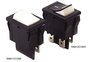
Above: Figure 4. The E-Switch RA8 series of rocker switches features a plastic separator to protect the two terminals from an accidental short circuit. The series has a wide variety of options including colours, straight or right angle terminals, and switch configurations. (Image source: E-Switch)
When dealing with high voltage switches, make sure to keep each connection separate to avoid accidental short circuits. The RA8 makes this easier by providing a plastic separator to keep the terminals physically apart.
Although wiring hot terminals is strongly discouraged, sometimes in a production environment it cannot be avoided. While the RA8 can lessen the chance of an accident occurring during hot wiring, take all safety precautions, including wearing insulated gloves.
Conclusion
Mechanical switches are appropriate for certain situations including control of high voltages, security, safety, ease of access, or a combination of these. There are many options for mechanical switches, and the right choice can provide peace of mind for both the designer and the end customer.
Featured products
| Manufacturer: | Texas Instruments |
|---|---|
| Part Family: | DP83TC811-Q1 |
| Status: | ACTIVE |
| ROHS: | Y |
| PB Free: | Y |
| Manufacturer: | Texas Instruments |
|---|---|
| Part Family: | UCC15240-Q1 |
| Status: | ACTIVE |
| ROHS: | Y |
| PB Free: | Y |

| Manufacturer: | Texas Instruments |
|---|---|
| Part Family: | TMP1827 |
| Status: | ACTIVE |
| ROHS: | Y |
| PB Free: | Y |
| Manufacturer: | Texas Instruments |
|---|---|
| Part Family: | SN74AHC1G02-Q1 |
| Status: | ACTIVE |
| ROHS: | Y |
| PB Free: | Y |
| Manufacturer: | Texas Instruments |
|---|---|
| Part Family: | DLP301S |
| Status: | ACTIVE |
| ROHS: | Y |
| PB Free: | Y |
| Manufacturer: | Texas Instruments |
|---|---|
| Part Family: | TMUXHS221LV |
| Status: | ACTIVE |
| ROHS: | Y |
| PB Free: | Y |