


This integrated project describes a dual CAN FD and LIN communication setup based on the ATA6586 System Basis Chip for reliable high-speed industrial and automotive communication.
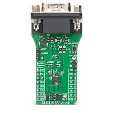
Featuring the ATA6586 from Microchip, the CAN-LIN SBC Click leverages a highly integrated SBC that consolidates a controller area network flexible data-rate (CAN FD) transceiver with partial networking, a local interconnect network (LIN) interface, and multiple voltage regulators into a unified hardware solution.
Additionally, the ATA6586 includes a high-speed CAN transceiver that supports standard CAN data rates up to 1Mbit/s and CAN FD data rates up to 5Mbit/s.
In an exclusive interview for Electronic Specifier, Mihajlo Đorđević, MIKROE’s Technical Content Manager, emphasised that CAN-LIN SBC Click represents a communication interface solution for advanced embedded systems, particularly those in automotive, industrial control, and networked automation environments.

Applications in automotive and industrial environments
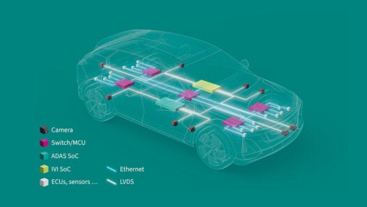
High-speed CAN FD and LIN are typically used together in systems that need a combination of fast data exchange and simple cost-efficient node communication, especially in environments exposed to vibration, temperature extremes, electrical noise, or strong EMI.
Djordjevic added: “Typical examples include automotive body electronics, distributed actuator clusters, HVAC control units, battery-related subsystems in electric vehicles, and industrial machines where mixed-network topologies are common.”
In these setups, CAN FD usually operates as the high-speed backbone for critical data transfer, diagnostics, and fast subsystem updates, while LIN handles smaller, local nodes such as actuators, position sensors, lighting modules, or simple electromechanical components.
“This makes CAN-LIN combinations particularly relevant for prototyping or evaluating architectures like multi-node actuator control, small gateway devices, body control modules, sensor clusters, and communication interfaces for machinery operating in noisy or harsh industrial conditions,” Djordjevic underlined.
Advantages of the high-speed CAN transceiver
The high-speed CAN transceiver inside the ATA6586 can be used to prototype and evaluate communication scenarios that require fast data exchange and strong fault-tolerance.
“Since the transceiver is fully compliant with ISO 11898-2:2016 and supports CAN FD data rates up to 5Mbit/s, it allows developers to explore high-bandwidth features such as rapid diagnostics, frequent status updates, or streaming larger data segments between nodes,” Djordjevic said.
Additionally, its wide common-mode range, autonomous bus biasing, and built-in dominant time-out protection help maintain stable communication even in noisy environments or during transient conditions on the bus.
Featured use cases
Mixed CAN and LIN communication is typically required in systems that combine a high-speed control or diagnostic backbone with multiple low-speed peripheral nodes.
“A common example is an automotive body-electronics architecture, where a CAN FD network coordinates modules such as door units, lighting controllers, HVAC systems, or seat mechanisms, while each of those modules includes several LIN-based actuators and sensors,” Djordjevic explained.
Another use case appears in distributed actuator clusters, where a central CAN controller supervises several LIN nodes such as small motors, position sensors, or interior-comfort components organised as local sub-networks.
“Electric vehicles often rely on this structure as well, integrating LIN nodes for auxiliary or comfort functions into a higher-speed CAN FD system that handles critical data flow,” Djordjevic said.
In industrial automation, mixed CAN-LIN networks show up in modular machines, robotic subsystems, or conveyor platforms, where CAN handles real-time coordination and diagnostics, while LIN nodes manage simple actuators, indicator modules, and local sensors.
“These scenarios demonstrate why combining CAN FD and LIN communication is valuable whenever a system needs both high-bandwidth, robust messaging and cost-efficient local control,” Djordjevic commented.
The interface between CAN and microcontrollers
The direct interface between a 5V microcontroller and the CAN bus is handled by the high-speed CAN transceiver integrated inside the ATA6586. From the MCU’s point of view, the connection is purely digital and uses standard logic-level signals, while all CAN-specific signal conditioning is managed internally by the transceiver.
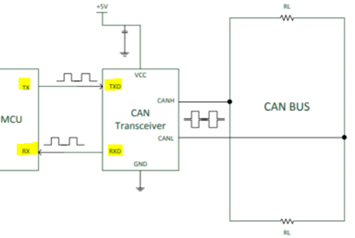
Djordjevic added: “In this setup, the microcontroller drives the TXD pin with a standard 5V digital signal. The ATA6586 converts this logic-level input into a differential CAN signal on CANH and CANL, which is suitable for transmission over the CAN bus.”
Meanwhile, on reception, the transceiver decodes the differential voltage on the bus and outputs a clean 5V digital signal on RXD, which the MCU can read directly.
“Because the CAN transceiver supports a wide common-mode range, autonomous bus biasing, and EMC/ESD protection, the microcontroller remains electrically isolated from disturbances on the CAN bus,” Djordjevic explained.
This allows reliable communication without external level shifters or additional driver circuitry, while maintaining full compatibility with 5V MCU designs.
The remote wake-up feature on the CAN-LIN SBC Click
The remote wake-up feature on the CAN-LIN SBC Click is used to bring the system out of a low-power or standby state in response to activity on the communication bus or a dedicated wake signal.
“This functionality is provided by the ATA6586 System Basis Chip, which supports both local and remote wake-up mechanisms. Remote wake-up can be triggered either by bus activity on the CAN or LIN interface, or via the dedicated WUP (Wake-Up) pin, depending on the system configuration,” Djordjevic underlined.
When the device detects a valid wake-up event such as a CAN bus activity, a LIN wake-up pulse, or an external signal on the WUP pin, it automatically transitions from low-power mode to normal operation.
“At the same time, the ATA6586 reactivates the transceivers and enables the internal regulators, allowing the host MCU to resume operation and process incoming data. In practical terms, this allows a system to remain in a power-saving state while still being responsive to network communication or external events,” Djordjevic said.
Applications of the integrated LIN transceiver in vehicle electronics
The integrated LIN transceiver is typically used in body electronics and other low-speed vehicle subsystems where simple, reliable communication is required without the complexity or bandwidth of high-speed networks.
Djordjevic added: “In automotive body electronics, LIN is commonly applied to functions such as door modules, window lifters, mirror adjustment systems, seat control units, interior lighting, and HVAC flap actuators.”
These subsystems usually consist of small actuators and sensors that operate at modest data rates and benefit from LIN’s single-wire topology and deterministic behaviour.
“Beyond classic body electronics, LIN transceivers are also used in auxiliary and comfort-related subsystems, including climate control peripherals, switch panels, steering-wheel controls, and small distributed sensor or actuator nodes,” Djordjevic explained.
In these scenarios, the LIN transceiver provides a cost-efficient and low-emission communication link that integrates easily with a higher-level controller, typically connected to a CAN backbone.
Communication with a host MCU via the SPI interface
The SPI interface on the CAN-LIN SBC Click enables direct, low-latency communication between the host microcontroller and the ATA6586 System Basis Chip.
“Through SPI lines (CS, SCK, SDO, and SDI), the MCU can access control and status registers inside the device, allowing software-based configuration and real-time monitoring of the transceiver and power-management functions,” Djordjevic underlined.
Using SPI commands, the host MCU can configure operating modes, enable or disable CAN and LIN transceivers, manage low-power states, and control wake-up behaviour.
“Status information such as fault conditions, wake-up events, or operating state transitions can also be read back over the same interface. This direct digital connection allows the MCU to fully manage the device without additional external control circuitry,” Djordjevic commented.
The key function of the VSENS pin
The VSENS pin on the CAN-LIN SBC Click provides an auxiliary regulated voltage output intended to supply external sensors or low-power peripherals directly from the ATA6586.
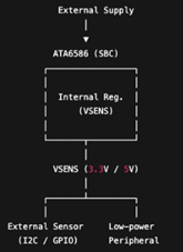
Djordjevic added: “This output can be configured to deliver either 3.3 or 5V (depending on the device configuration) with a current capability of up to 30mA, making it suitable for small sensors or lightweight peripheral circuits.”
In this arrangement, the ATA6586 generates a stable auxiliary supply on the VSENS pin, which can be routed directly to external sensors or peripheral devices mounted off-board.
“This eliminates the need for an additional external regulator when powering low-current components. The host MCU continues to communicate with these peripherals through its interfaces such as I²C, SPI, or GPIO, while VSENS provides a power rail,” Djordjevic said.
Final considerations
In summary, the CAN-LIN SBC Click brings together high-speed CAN FD communication, a fully compliant LIN interface, and integrated power-management features within a single, compact solution.
“By combining robust transceiver performance, flexible wake-up mechanisms, SPI-based control, and auxiliary power outputs, it enables engineers to explore, develop, and integrate mixed CAN/LIN communication architectures with minimal external components,” Djordjevic underlined.
The board highlights how modern System Basis Chips such as the ATA6586 simplify system design by handling communication, diagnostics, and power distribution in one device.
“This makes the CAN-LIN SBC Click a practical platform for working with dual-network topologies commonly found in automotive body electronics, electric vehicle subsystems, and industrial control systems, while offering a clear and accessible path from concept to implementation,” Djordjevic concluded.