Two-node scheme transformations

Let us consider the circuit in Figure 27a.

Circuit Fundamentals - Fig27
Figure 27

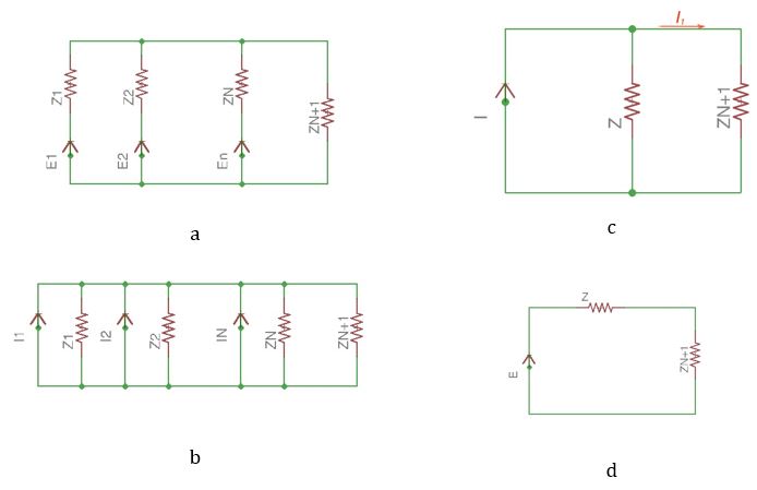
Converting voltage sources to the current sources we achieve the scheme in Figure 27b. All the current sources are form one equivalent current source I, where:

I=I1+I2+...In=E1Z1+E2Z2+...EnZn=k=1nYkZk, and Z=1k=1Ykn

Thus:

E=ZI=k=1YkZknk=1Ykn

This means that n parallel voltage sources can be replaced with one current source or voltage source.

Current in the external network is the following:

In+1=IZZ+Zn+1=EZ+Zn+1

Voltage between two nodes can be found the following way:

U=IZZn+1Z+Zn+1=I1k=1n+1Yk=k=1nEkYkk=1n+1Yk

Shifting sources in an electric circuit

Keep Up to Date with the Most Important News

By pressing the Subscribe button, you confirm that you have read and are agreeing to our Privacy Policy and Terms of Use
Previous Post

Secure authenticator protects device stored data

Next Post

Image signal processor powers video recording eyewear