


This article originally appeared in the May ’22 magazine issue of Electronic Specifier Design – see ES’s Magazine Archives for more featured publications.
DC voltages in energy storage systems have continued to climb with 250, 600, 1000V DC and beyond employed. Battery systems should match the input DC voltages of the latest inverters and converters and most utility-scale solar inverters and converters now use 1500V DC input from solar panels.
To find components that support both higher DC voltages and also provide embedded protection features, energy system designers should look for insulated magnetics products rated at 1500V DC. It is also important is to specify a signal transformer that integrates a common mode choke to meet the demanding isolation and EMI filter requirements on isoSPI communication buses in a battery energy storage system (BESS).
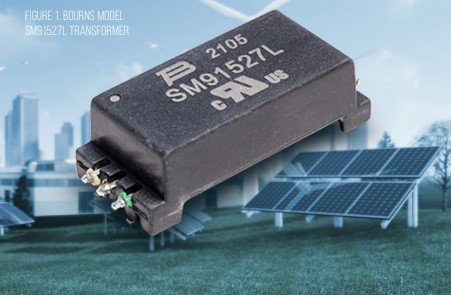
Figure 1 (above) shows the SM91527L transformer which has UL approval and a creepage of 15mm between primary and secondary. This enables use in environments requiring reinforced isolation with working voltages of 1500V. The transformer also meets isoSPI driver recommendations in terms of insertion loss (max 1.2dB at 4MHz) and EMI (−50dB 1.0 to 100MHz CMRR).
Taking this design approach, it is important to note that the battery management system (BMS) interface is operating in a non hazardous environment separately from the battery pack voltage. At the same time, it should provide the necessary matching and common mode noise removal so that the communications between the monitoring ICs and the central management board are also secure and uninterrupted.
Transformers with reinforced insulation up to 1500V must pass tests as defined by IEC 60664 to prove the insulation will survive sudden surges. Consumer and industrial equipment need to be rated to different categories and level of surge testing required is determined during qualification.
Surge tests are used to primarily check that there is adequate clearance, so that if an event, such as a lightning strike, were to occur, the gap between the windings on the transformer would not break down and ionise causing a crossover. To be rated at 1,500V for an over-voltage category 2 up to a 5,000m altitude, the reinforced transformer must be able to withstand an impulse test of 12kV peak.
Mandatory tests check the quality of the insulation material. Reinforced insulation is checked by applying a DC or AC voltage between the primary and secondary side and measuring the amount of leakage current between the two. This is known as a dielectric or hi-pot test; the permittivity of the insulation material will accumulate charge, which translates into a leakage current.
A partial discharge test is also required in systems with working voltages higher than 750V DC. This puts the transformer through an ageing process using high temperature and humidity. The DC voltage is ramped up from zero to a value dependent on the working voltage while measuring the amount of charge in coulombs gathered in the insulation.
It has become a requirement to use transformers with reinforced insulation at the point of entry into networks, especially if the battery management board could be exposed to enable testing and diagnostics by a technician. If the racks that hold battery modules are shielded by plastic walls and use transformers for communications in a daisy chain configuration, they will not require reinforced insulation.
For this application, signal transformers with functional insulation for 1500V can be used, such as the SM91501ALO transformer, which has two channels instead of one and is suitable for placement in the middle of a daisy chain. Hi-pot and impulse tests are still required but the procedure is less severe (4.3kV DC hi-pot and 8kV impulse).
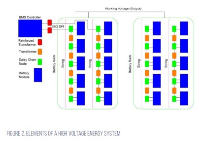
Figure 2 illustrates where the reinforced single-channel transformer and the functional two-channel transformer would be located in a 1500V BESS. The battery energy storage system is divided into strings of 50V battery modules. Within this string, each module is monitored and each has a two-channel functional insulation transformer in the isoSPI bus. This configuration enables the string to be protected with the reinforced single-channel magnetics component.