


Profibus is the world’s most accepted field bus with over 50 million nodes in operation. Originally developed in Germany and registered as DIN 19245 in 1989, the International Electrotechnical Commission (IEC) recognises Profibus and its various interconnection formats in IEC 61158.
The name is derived from the term process field bus. Designed initially as a bit-level serial communications standard, Profibus co-ordinates process steps via information exchange between the various nodes in a networked system. The original Profibus field management system (FMS) was succeeded by simpler and faster protocols, such as Profibus distributed peripherals (DP), Profibus process automation (PA), and ProfiDrive, aimed solely at motor control.
Profibus DP is, by far, the most popular implementation, and its strong growth is continuing. However, as the number of new DP network installations keep rising, so do their application specific requirements. Amongst these are higher operating temperatures and isolation voltages, as well as smaller form factors. While many RS-485 transceivers claim to be Profibus compatible, only a small number are truly standard-compliant, and even fewer satisfy the increasingly harsher system requirements.
This article describes best practices for new designs of Profibus DP nodes, and covers bus node isolation, Profibus compliance, bus signal polarity and how to protect an isolated bus node against ESD, EFT, and surge transients.
A new family of Profibus internationally recognised isolated transceivers, will also be covered. Their isolation technology is based on giant magneto resistance (GMR). This family includes what is claimed to be the industry’s smallest, as well as most robust, Profibus transceivers.
Traditional isolation
Figure 1 shows the traditional isolated bus node design depicted in all Profibus DP documentation. This circuit uses three optocouplers to separate the Profibus transceiver from its earth ground referenced controller circuit.
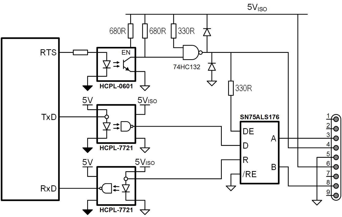
Figure 1: Traditional Profibus DP node
Renesas integrated GMR isolators with Profibus RS-485 transceivers to produce the ISL32740 transceiver. The device reduces component count and power consumption while boosting the tolerance to common-mode voltages and line noise. In addition, the transceiver significantly improves reliability. Since there is no wear out mechanism in GMR isolators, the device will outlast the lifetime of applications without replacement. Figure 2 shows a typical DP node design using the ISL32740.
Compliance and approval
Profibus International places limits on transceiver differential output voltage that prohibit the use of many transceiver chips on the market today. Under no-load condition, the maximum differential bus voltage is limited to 7VPP, while for maximum load, the minimum limit is 4VPP.
Many RS-485 transceivers with high output drive comply with the minimum value of 4VPP, but exceed the less obvious maximum of 7VPP, because it is easy to produce drivers with differential voltages of up to 8.5V. In this case, more is not better.
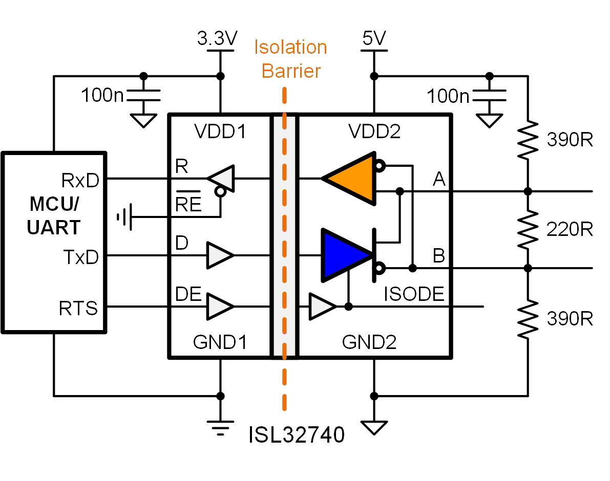 Figure 2: Modern Profibus DP node using the ISL32740
Designers should be aware that failure to use a transceiver complying with the 4VPP to 7VPP limits will cause any product offered up for Profibus certification to be rejected by the approval body. Another hurdle is the requirement of measuring the differential voltage at the maximum specified power supply voltage. For a 5V transceiver, this usually is 5.5V. Profibus test laboratories use that worst-case voltage in compliance tests.
The RS-485 standard clearly defines the transceiver bus terminals A and B as the inverting and non-inverting terminals, respectively. However, all transceiver manufacturers use the opposite convention with terminal A being the non-inverting and terminal B as the inverting terminal.
With history repeating itself and thus maintaining a matter of consistency, Profibus uses EIA-485 as written and assigns the non-inverting terminal to the B wire and the inverting terminal to the A wire. However, worldwide transceiver manufacturers continue to use the opposite signal convention.
The discrepancy between specified and actually applied signal conventions has always been confusing to network designers, however, the solution to this problem is simple. Stick to the signal convention of the transceivers making up the 50 million Profibus nodes installed so far, with A as the non-inverting and B as the inverting terminal. This ensures the design is compatible with the next 50 million nodes of future installations.
A GMR Profibus
Since the introduction of the non-isolated ISL3159 Profibus transceiver, Renesas has integrated this device with digital isolators (based on GMR technology) into single packages to produce the ISL3274x family of isolated Profibus transceivers. The initial ISL32740EIBZ design addresses applications requiring true 8mm creepage distance, and standard industrial temperature range from -40 to +85°C.
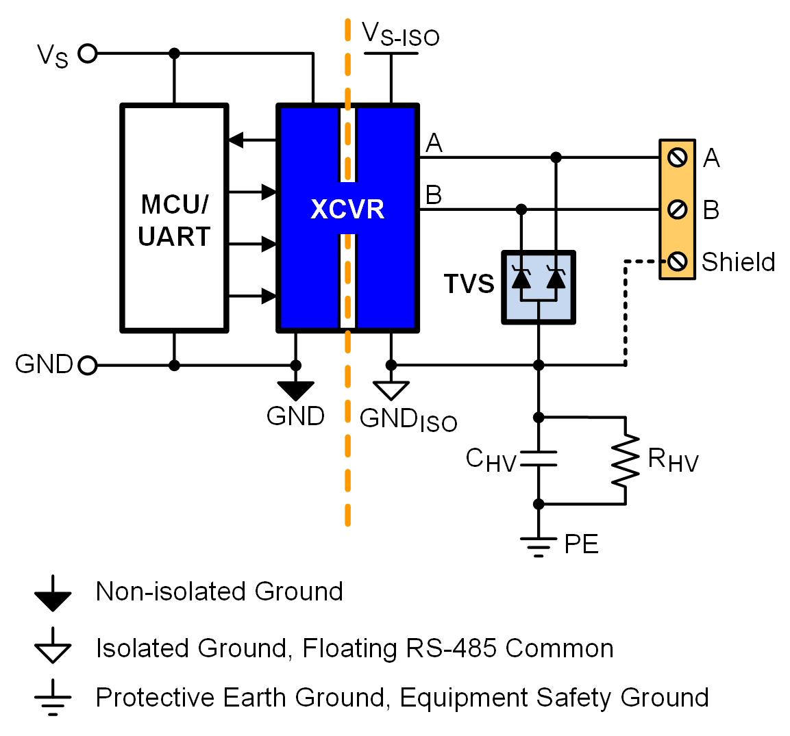 Figure 3: Isolated Profibus DP node with transient protection
For dense designs necessitating small form factor packages, the same solution was implemented into a tiny 16-lead QSOP. The operating temperature range from -40 to +85°C is still maintained. Discussion with Profibus customers established the need for higher ambient temperatures of 115 and 125°C in future designs. Here, the 8mm, 16-lead wide body SOIC package provides sufficiently low thermal resistance to allow for reliable operation at 125°C, albeit at a slightly lower yield. This resulted in the release of the high-temperature Profibus isolator ISL32740EFBZ.
The real design challenges however, came from customers working in medical and robotics applications. These call for higher temperatures but also for VDE reinforced isolation, which led to the designs of the ISL32741EIBZ and ISL32741EFBZ that use 6kV isolators for the industrial and extended industrial temperature range, respectively. While these applications commonly use RS-485 and not Profibus DP as their physical layer, Renesas’ Profibus transceivers comply with both standards. Table 1 lists the various Profibus transceivers.Note that all transceivers support a maximum data rate of 40Mbit/s while operating from a primary supply of 3.0 to 5.5V, and from a secondary supply of 4.5 to 5.5V.
|
DEVICE |
Working Voltage (V) |
Isolation Voltage (kV) |
Isolation Grade |
(oC) |
Package (16 Leads) |
Dimensions (mm x mm) |
|
|
ISL32740EIAZ |
600 |
Basic |
-40 to 85 |
QSOP |
4 x 5 |
||
|
ISL32740EIBZ |
600 |
Basic |
-40 to 85 |
SOIC-W |
|||
|
ISL32740EFBZ |
600 |
Basic |
-40 to 125 |
SOIC-W |
|||
|
ISL32741EIBZ |
1000 |
6 |
Reinforced |
-40 to 85 |
SOIC-W |
||
|
ISL32741EFBZ |
1000 |
6 |
Reinforced |
-40 to 125 |
SOIC-W |
Table 1. Isolated PROFIBUS transceivers
Transient protection
Protecting the ISL32740E against transients exceeding the device’s transient immunity requires the addition of an external transient voltage suppressor (TVS). For this purpose, a Semtech RClamp0512TQ was selected due to its high transient protection levels, low junction capacitance, and small form factor.
|
PARAMETER |
SYMBOL |
VALUE |
UNIT |
|
|
ESD (IEC61000-4-2) |
Air |
VESD |
±30 |
kV |
|
Contact |
VESD |
±30 |
kV |
|
|
ESD (IEC61000-4-4) |
VEFT |
±4 |
kV |
|
|
ESD (IEC61000-4-5) |
VSurge |
±1.3 |
kV |
|
|
Junction Capacitance |
CJ |
3 |
pF |
|
|
Form Factor |
– |
1 x 0.6 |
mm |
|
Table 2. RCLAMP0512 TVS features
The TVS is implemented between the bus lines and isolated ground (GNDISO) as shown in Figure 3. Since transient voltages on the bus lines are referenced to earth potential (or protective earth, PE), a high-voltage capacitor (CHV) is inserted between GNDISO and PE, providing a low-impedance path for high-frequency transients. Note that the connection to PE is usually made via the metal chassis of the equipment, or a short, low-inductance wire.
A high-voltage resistor (RHV) is added in parallel to CHV to prevent the build-up of static charges on floating grounds (GNDISO) and cable shields (typically used in Profibus). The bill of materials for this circuit is listed in Table 3.
|
NAME |
FUNCTION |
ORDER NO. |
VENDOR |
|
XCVR |
Isolated 40Mbps RS-485/PROFIBUS Transceiver |
ISL32740EIAZ |
Renesas |
|
TVS |
170W (8, 20µs) 2-Line Protector |
RCLAMP0512TQ |
Semtech |
|
CHV |
1812B472K202NT |
Novacap |
|
|
RHV |
1MΩ, 2kV, 5% Resistor |
HVC12061M0JT3 |
TT-Electronics |
Table 3. Bill of Materials
Many devices will function in a Profibus DP node but only a handful will meet the 7VPP DP maximum differential voltage specification. The ISL3274xE isolated transceivers meet the Profibus specifications and are recognised for use in DP nodes by Profibus International. They eliminate design risk and accelerate time to market using GMR isolator technology for basic and reinforced isolation.
Visit Renesas at PCIM 2018
Hall 9-628