


Today’s consumers are seeking and embracing new technology more eagerly than ever before. As they upgrade devices such as smartphones, smart watches, tablets and wearable fitness bands, performance expectations rise with each new product generation. Not only do consumers demand enhanced functionality, they are expecting the devices to be smaller, faster and have longer runtimes than the previous generation.
While this desire to have the latest products fuels the business of technology companies, it also creates challenges for the engineers tasked with delivering the new designs. In order to create high density circuitry and increase runtimes, efficiency must be improved. However, as designs feature electronics that are miniaturised and very closely packed, it is increasingly important not to cut corners with regard to electromagnetic interference (EMI) -related matters.
Power conversion
One thing that all of these portable devices share is that they are powered by some form of battery. The voltage directly from the battery however is unlikely to be what the semiconductors that form the heart of product design need to operate, so conversion is needed to change (and stabilise) the voltage to the correct level.
The so-called buck converter has become popular as it provides a simple, relatively efficient way of converting a battery voltage into a stable supply for semiconductors. Buck converters operate by ‘chopping’ the DC voltage from the battery to change the level, but in doing so, have the potential to introduce EMI-related issues.
While EMI can be a complex subject, there are a number of areas where a designer should focus in most buck converter designs, namely, layout for current loops, component placement, output ripple voltage, input capacitor selection and radiated EMI suppression.
In order to reduce the size of power converters, and the associated magnetic components, it is common to use higher switching frequencies. However, as the rate of change of current (di/dt) increases, so does the potential for EMI. To minimise these effects, it is important to understand how the current flows between components. Once the current paths are clear, designers should ensure that all return current paths are as short and as low impedance as possible, especially the ground traces.
 Figure 1: The buck converter is a popular solution for DC distribution in system design
Current flow, along with the topology chosen (in this case, a buck topology) also plays an important role in determining component placement.
One key consideration is ensuring that the capacitors and inductors are placed to minimise the current loop. In doing so, the input power traces will need to be routed. Here, designers should ensure that the inductance of these traces is greater than the equivalent series resistance (ESR) of the input capacitors – explaining why low ESR capacitors are a good choice.
Capacitor choices
Capacitor selection should not be neglected by designers. Capacitors form an important part of power converters and selecting capacitors with high energy capability such as Kemet’s KO-CAP polymer capacitors, or low ESR multi-layer ceramic capacitor (MLCC) devices is good practice. Combining the two types will reduce ripple voltage and minimise the component count.
When selecting the input capacitor, it should also be remembered that the output current directly affects the input ripple voltage. Defining the transient current requirements can be challenging, but is an important step in the design process as it directly impacts the choice of input capacitor.
In general, current is the primary consideration when addressing EMI, although a large ripple voltage can significantly contribute to EMI issues. The AC current through the power inductor flows into the output capacitor where (according to Ohm’s Law) the ESR will generate a ripple voltage. Hence, selecting an output capacitor with a low ESR will reduce the output ripple voltage.
Conducted EMI is generally the most common issue within buck converter designs. However, radiated EMI is also an issue, particularly in densely-packed designs such as modern consumer devices. While techniques such as good layout and trace design can reduce this issue, it cannot be avoided completely.
Ferrite devices, such as Kemet’s Flex Suppressor products are very useful to create in-circuit barriers, effectively isolating sensitive circuit areas from other sections that may be coupling unwanted radiated noise.
Efficient design
Having addressed the potential noise issues, consideration needs to be given to the overall efficiency of the buck converter design. A more efficient design allows for longer runtimes and, as less heat is produced, components can be placed closer together, allowing designers the flexibility to shorten traces to address EMI.
Power engineers rely on the buck controller IC, along with a well-specified power inductor to minimise losses and increase efficiency. Selecting an inductor that can operate at high frequencies while offering high current saturation characteristics and low DC resistance (DCR) is essential to efficient buck converter design.
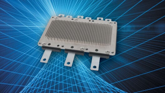
Inductors from the new Metcom series are effective in supporting the development of more efficient buck converters as well as being suitable for use in other power-related applications including EMI filtering. The metal composite core offers high current saturation characteristics that allow the inductors to maintain function with large ripple currents. High permeability enables low values of DCR that result in significantly reduced self-heating during high current operation, thereby increasing system efficiency and reducing the need for thermal design considerations.
Metcom inductors have a shielded construction, thereby containing most of the magnetic flux within the inductor body, leading to more efficient operation. This enhances radiated EMI performance and significantly reduces RF coupling with nearby circuit areas.
The inductors range in value from 0.10 to 47.00mH, with DCR values down to 1.5mW. They can handle currents as high as 35.4A and operating temperatures between -55 and +155°C. Footprints can be as small as 5.3 x 5.00mm and profiles as low as 2.0mm, making them well-suited to densely-packed circuits in modern power applications.
Power conversion is essential for delivering the high-tech devices that we have all come to rely on in connected day-to-day lives. Increasing efficiency and controlling EMI are key challenges for designers trying to create ever more dense designs. However, by following good design practices and selecting components carefully, these challenges can be mitigated.