


Electric components in vehicles were first introduced in 1915, when Ford Motor Co. introduced electric lights and an electric horn to its Model T automobile. Since then, the dependence on electrical and electronic systems in automobiles has been steadily increasing. The initial systems tended to be local and independent – a switch that controlled the headlights connected directly to the battery, or a relay controlled a monotonous speaker.
As architectures have evolved, so have the mechanisms through which various subsystems within the car communicate. As the car detects reduced ambient light outside the vehicle, for example, it may automatically enable the headlamps, but that’s not all. It would likely adjust the brightness levels on all displays, tweak the white balance of all cameras, increase the distance maintained from the vehicle in front, and add greater emphasis to braking modules, all to create a safer driving experience.
As the pursuit of autonomous vehicles continues, there is greater onus on communication to be safe, secure, and as real-time as possible. This challenge is only exacerbated by the fact that the quantity of data transmitted and received is no longer in the hundreds of kilobits per second, but in tens of gigabits per second.
In this paper, four automotive communication protocols are examined: the Ethernet, FPD-Link technology (a proprietary automotive serialiser/deserialiser (SerDes) protocol), CAN bus and the PCIe bus, highlighting core nuances of each technology and offering examples and the features where these technologies support modern automotive driver assistance systems (ADAS) architectures as illustrated in Figure 1.
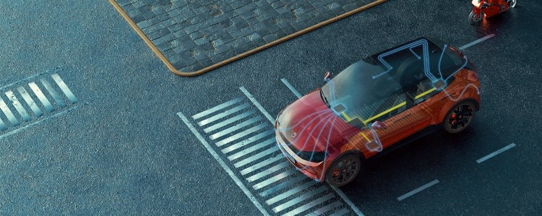
Figure1. Communication protocol technology highlighted within a vehicle
Ethernet
Ethernet is one of the most common high-speed interfaces found in homes and offices and is becoming a predominant communication protocol for vehicles. Some vehicles use Ethernet to transport a variety of high-speed data; automotive applications such as radar and lidar modules use single-pair Ethernet technology. Single-pair Ethernet uses the Ethernet standard, but data transmits over a single, twisted pair of wires, enabling reduced cable weight and cost within the vehicle.
Ethernet is a packetised system, where packets between nodes on various parts of the network transfer information. Also like a CAN bus, Ethernet is bidirectional, and the speed possible on any individual link decreases as the number of nodes on the system increases. For single-pair Ethernet, the speed on any individual link is limited to one specific speed (10 Mbps, 100 Mbps, 1 Gbps) and no dynamic speed changes on the link may occur. Still, single-pair Ethernet can transport data over a link up to 1,000 times faster than a CAN bus. Changing to single-pair Ethernet would optimize the data transmission speed over a CAN bus, but since Ethernet’s cost per node is higher, it probably will not replace – but rather will augment – a CAN bus.
Some cars today use single-pair Ethernet for data- intensive requirements such as backup cameras and radar. For example, the DP83TC812S-Q1 and DP83TG720S-Q1 from Texas Instruments (TI) are single- pair Ethernet physical layers (PHYs), screened to Automotive Electronics Council-Q100 grades 1 and 2, and include a loopback test mode for facilitating system diagnostics compliant to Institute of Electrical and Electronics Engineers (IEEE) 802.3bw and 802.3bp automotive standards. To transport video over an Ethernet network, even if there is only one video channel being transported, the video must be compressed at its source and then decompressed at the destination to avoid exceeding Ethernet bandwidth limitations unlike FPD-Link technology, which allows for uncompressed transport of video data. For an application such as a backup camera, there needs to be a relatively high-power processor in the camera to compress the image sufficiently to get it into the Ethernet network.
The need for a high-power processor in turn means that the camera will be physically larger and more expensive. The camera will have a higher power dissipation than an approach that does not require much image processing. Another disadvantage of this solution is that video compression and decompression add latency to the link. If several cameras or other video sources are sharing the same Ethernet network, there is a trade-off between the amount of compression (and corresponding video quality) and the number of supported video channels. It is possible to mitigate this limitation by setting up multiple networks within the car in a hierarchical configuration. There might be one network that deals only with engine control and diagnostics, a second network that handles backseat entertainment and the audio system, and another network that handles driver assistance functions such as vision enhancement cameras. In the end, single-pair Ethernet provides higher capacity than the CAN bus for transmitting data like radar and lidar, at the expense of greater complexity, but still struggles to handle the highest-bandwidth applications such as video.
FPD-Link technology
FPD-Link is a proprietary automotive SerDes technology developed for real-time, uncompressed transmission of high-bandwidth data. Specifically, FPD-Link was developed to transport video data within the car, which has enabled enhanced data analysis and processing in driver assistance applications. For example, it can be used to send uncompressed video to a display while the back channel sends information from an external-facing camera to the processor, which uses image processing and algorithms to send a command signal back to the car or driver, such as for automatic braking. The physical layer for FPD-Link is either a twisted-pair or coaxial cable. The wiring is dedicated, so when using FPD-Link for a backup camera, one cable goes from the camera to a processor and a second cable goes from the processor to the display in the cabin. The big advantage of using FPD-Link in this application is that both the camera and display can be much simpler circuits, since compression and decompression are not required.
Additionally, since the links are dedicated, the image quality of one video system is independent of what else is going on in the vehicle. FPD-Link has a forward channel bandwidth of 25 Gpbs+ and a simultaneous low- speed back channel. The back channel can be used to transport an I2C bus at 400 kbps or it can control GPIO lines at rates of up to 1 Mbps. It is possible to use the back channel to configure a camera, operate a zoom lens or send touchscreen information back to a controller without interrupting video flow on the forward channel.
For autonomously-driven vehicles, another important factor will be the amount of latency in the link. The processing required to compress and decompress an image adds to this latency. For an application such as backseat entertainment, a delay between reading the data from a DVD and its display on the screen is not important. If the image being transported is from a camera looking for pedestrians in the path of the vehicle, however, latency may have dire consequences. FPD-Link is perfect for links where high bandwidth and low latency are the most important factors. Additionally, the ability to support a back channel and power over a single twisted- pair or coaxial connection simplifies the wiring and can help reduce the complexity of the overall system design.
Figure 2 shows an OMAP video processor connected to two different cameras and a display with a single twisted-pair cable going to each peripheral. This twisted- pair cable supports camera video data and touchscreen or camera-setup data. The cable can also provide power for the display or camera. Since each link is dedicated to one peripheral, it eliminates risk of interference between the signals from the two cameras, improving data integrity for processing and analysis, making ADAS capabilities more reliable and accurate.
The ability to transmit data from multiple cameras is particularly beneficial to surround-view applications like automated parking, where a 360-degree view of a vehicle’s surroundings can give drivers critical information for a safer driving experience. Learn more about the foundations of FPD-Link by watching What is FPD-Link?
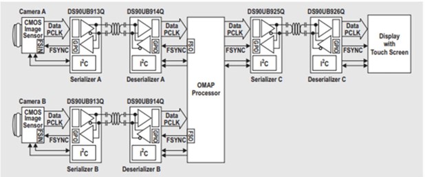
Figure2. Multi-camera system with FPD-Link
CAN bus
CAN communication has greatly evolved since its development by Robert Bosch GmbH in the 1980s.
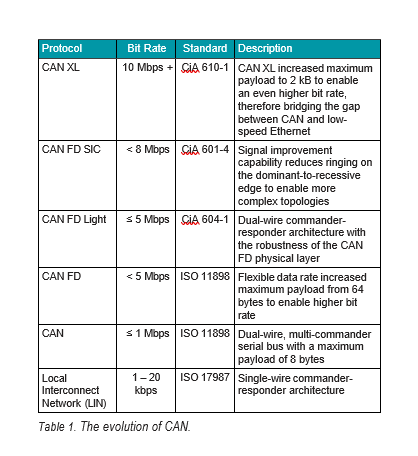
The multidrop network protocol significantly reduced the cable wiring required in the vehicle, while also enabling an arbitration communication system that grants bus access to the highest-priority node on the bus. The CAN protocol and physical layer were originally standardized in the early 1990s for data rates up to 1 Mbps. Today, CAN communication has advanced to speeds up to 10 Mbps, bridging the gap between 1990s Classical CAN and low-speed automotive Ethernet such as 10Base-T.
CAN is a multi-commander serial bus; in other words, no single commander node controls when individual nodes can read and write to the CAN bus. Each message frame contains an identifier that establishes the priority of the CAN message. If multiple nodes try to transmit to the CAN bus at the same time, the node with the highest priority (or lowest arbitration ID) will take control of the bus. CAN communication is reliable in harsh environments, and it allows ECUs to communicate with only a single pair of wires.
When CAN was originally developed in the 1980s, the number of ECUs in a vehicle was relatively low. Today, passenger vehicles can now contain more than 100 ECUs, controlling functions that range from essential power steering to luxury features such as seat massagers and steering wheel heaters. With the increase of ECUs and the need for more advanced safety features in passenger vehicles, CAN communication has evolved as well.
Table 1 lists more information about CAN communication networks, including new standards such as CAN FD Light, CAN Signal Improvement Capability (SIC) and CAN Extra Long (XL). Learn more about CAN by reading Introduction to the Controller Area Network (CAN).
PCIe technology
PCIe is a communication standard for bidirectional high-speed serial buses that meet high-bandwidth, ultra- low latency performance requirements. More commonly used in industrial application, PCIe is now emerging in automotive uses as manufacturers started rethinking the data backbone architecture in order to support the high-bandwidth and low-latency systems handling the exponential increase of sensor data and user information that requires real-time processing.
To solve this challenge, a centralised computing node supports many different types of domains (ADAS, infotainment, powertrain). This centralised computing box would typically include many modules that support different functions of the car, giving car manufacturers the flexibility to scale up and down and customise features of the car without redesigning the entire domain controller. Because PCIe supports one root complex or central processing unit (CPU) to many end points or receivers, having a centralised and modular design with PCIe can significantly reduce the overall ECUs and cables needed in a car.
When the automotive industry started requiring coprocessing and redundancy across the data backbone, PCIe became increasingly attractive because many CPUs have a native PCIe interface built in and do not require additional interface conversions across the backplane. PCIe has a huge ecosystem with open software resources and has consistently doubled its bandwidth from generation to generation, with very scalable bandwidth. It is thus possible that the PCIe protocol can keep up with the bandwidth required by the exponential growth in automotive data processing.
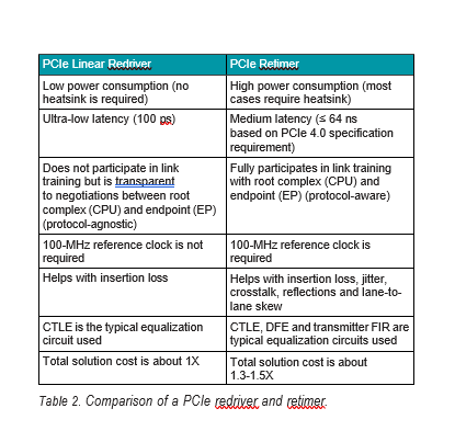
When designing a high-speed data signal path, signal degradation can become a huge challenge. A signal conditioner such as a redriver or retimer may be necessary to recover and compensate for the insertion loss and noise from printed circuit board material, vias, connectors or across cables. Both redrivers and retimers have a reliable and long history in the PCIe ecosystem, improving the overall signal integrity for transporting data through the PCIe protocol. Table 2 lists the differences between a redriver and retimer. Learn more about the elements that make up the PCIe signal path by watching the video, Solving PCIe signal integrity challenges.
Conclusion
Which interface is best for automotive communications? They all are – but each for its own purpose. When bandwidth requirements move up, such as for radar and LIDAR data transmission, Ethernet supports necessary bandwidth requirements. When the highest bandwidth and lowest-latency link are required, such as for a surround-view camera system providing input to an autonomous vehicle, then FPD-Link is ready to meet the challenge. The CAN bus continues to provide ADAS support for low-speed control applications where cost is a driving factor, such as data prioritisation, airbag deployment, and more. PCIe can meet the demands for moving the ever-increasing amount of sensor data and user information that require real-time processing. Together, these four critical automotive communication protocols build an integrated, connected vehicle that supports driver safety in real time and meets the ever-growing requirements of ADAS architectures. Learn more about how our advanced communication technologies improve reliability for safety-critical driver assistance applications at Sensor fusion.