Protect your LED designs from over-voltage transient surges
Growth in demand for LED lighting is accelerating as consumers and industrial users seek more energy-efficient illumination options. Growth is also being driven by government actions designed to discourage continued usage of incandescent lamps. This means the high adoption rate of LED lighting is definitely a global phenomenon.
By Teddy To, Technical Marketing Manager, PLED LED Protection Devices, Littelfuse.
Countries with the most advanced economies have well-established plans and programmes to phase out incandescent lighting. That shouldn’t be surprising given that lighting accounts for about 25% of global energy consumption.
With technological revolutions in LED efficiency (lumens per watt), secondary optics (lenses/reflectors) and thermal dissipation, LED lighting is increasingly replacing legacy light sources (mercury vapour, metal halide and sodium vapour) in outdoor applications. Nevertheless, the initial cost of outdoor LED lighting is high and payback is established based on lower wattage demand, lower maintenance cost and longer lifetime. In order to protect outdoor LED lighting from experiencing failures within an investment payback period of about five years, the lighting should have high durability and reliability. One significant threat to outdoor LED lighting is transient surge events in AC power lines that can damage lighting fixtures.
Indirect lightning-induced surges
Over-voltage transient surges can occur in AC power lines as the result of nearby electrical equipment being switched on/off. Nearby lightning strikes can also generate transient surges in AC power lines, especially in outdoor environments.
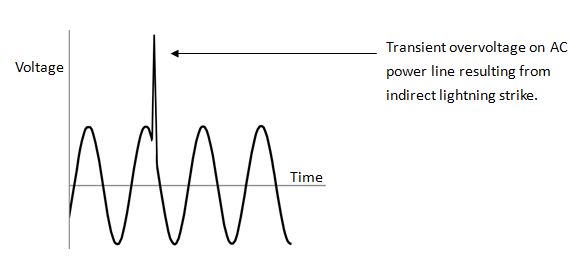
This type of indirect lightning energy from storms can adversely affect outdoor LED lighting installations. The luminaire is susceptible to damage both in the differential and common modes:
- Differential mode – High voltage/current transient between the L-N or L-L terminals of the luminaire could damage components in the power supply unit or LED module board.
- Common mode – High voltage/current transient between the L-G (earth) or N-G (earth) of the luminaire could break over safety insulation in the power supply unit or LED module board, including the LED to heat-sink insulation.
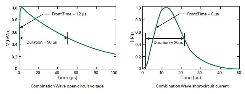
The test waveform is a combination 1.2x50μs open circuit voltage and 8x20μs short circuit current waveform. To perform this test, the specified peak current is calibrated on the surge generator by shorting the output to ground prior to connection to the luminaire.
Extracted from Littelfuse_LED_Lighting_Design_Guide.pdf
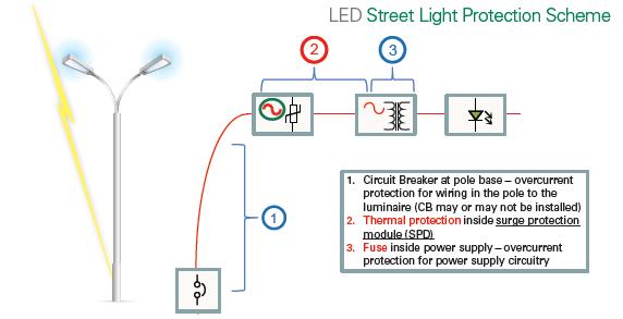
Incorporating a robust surge suppression circuit in an outdoor luminaire can eliminate damage caused by surge energy, thereby enhancing reliability, minimising maintenance and enhancing the useful life of the lighting installation. A surge protection subassembly that can suppress excessive surges to lower voltage levels is an optimal way to protect the LED luminaire investment.
Extracted from Littelfuse_Varistor_LSP05_LSP10_Surge_Protection_Modules_Flyer.pdf
Thermally protected MOV for SPD safety
Metal Oxide Varistor (MOV) technology is not only inexpensive but also a highly effective technology for suppressing transients in power supplies. It is also effective in many other applications, such as the Surge Protective Device (SPD) modules that are often placed in front of an LED driver.
MOVs tend to degrade gradually after a large surge or multiple small surges. This degradation leads to increasing MOV leakage current, which in turn raises the MOV’s temperature, even under normal conditions like 120/240VAC operating voltage. A thermal disconnect adjacent to the MOV can be used to sense the increase in MOV temperature while it continues to degrade to its end-of-life condition; at this point, the thermal disconnect will open the circuit, removing the degraded MOV from the circuit and preventing its catastrophic failure.
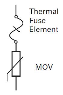
Extracted from Littelfuse_Varistor_TMOV_ITMOV_Datasheet.pdf
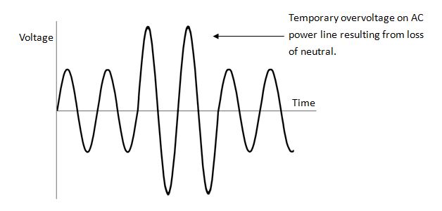
MOVs are designed to clamp fast over-voltage transients within microseconds. However, in addition to short duration transients, MOVs inside SPD modules can be subjected to temporary over-voltage conditions caused by loss of neutral or by incorrect wiring during installation. These conditions can severely stress an MOV, causing it to go into a thermal runaway condition; in turn, this will result in overheating, smoke and the potential for fire.UL 1449 and IEC 61643-11, the safety standards for SPDs, define specific abnormal conditions under which devices must be tested to ensure SPD safety. Robust designs include thermal disconnects within the SPD to protect the MOVs from thermal runaway.
End-of-life/replacement indication for SPDs
When an MOV gets overheated due to temporary over-voltage or excessive leakage current, a thermal disconnect may be used to help remove the MOV from the AC circuit. However, with the MOV removed from the circuit, the SPD no longer provides surge suppression. Therefore, proper indication should be considered so that maintenance personnel will know the SPD is not working and needs replacement.
Luminaire designers can choose from two main types of SPD module configurations based on their maintenance and warranty strategies.Those are parallel- and series-connected surge protection subassemblies.
Parallel connection – The SPD module is connected in parallel with the load. An SPD module that has reached end-of-life is disconnected from the power source while leaving the AC/DC power supply unit energised. The lighting still remains operational, but the protection against the next surge to which the power supply unit and LED module are exposed is lost. In a parallel-connected SPD module, replacement indication can be added through the use of a small LED that indicates the SPD module status to the maintenance technician. Options for a green LED indicating an online SPD module or a red LED indicating an offline SPD module are available. Or, rather than an LED indication at each lighting fixture, the need for SPD module replacement could be indicated remotely to a light management centre with SPD module end-of-life indication wires connected to a networked smart lighting system.
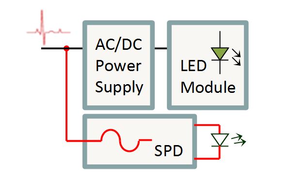
Extracted from Littelfuse_Varistor_LSP05_LSP10_Surge_Protection_Modules_Flyer.pdf
Series connection – The SPD module is connected in series with the load, where the end-of-life SPD module is disconnected from the power source, which turns the light off. The loss of power to the luminaire serves as indication for a maintenance call. The disconnected SPD module not only turns the lighting off to indicate the need for replacement but also isolates the AC/DC power supply unit from future surge strikes. General preference for this configuration is growing rapidly because the luminaire investment remains protected while the SPD module is awaiting replacement. It’s far less expensive to replace a series-connected SPD module than the whole luminaire as in the case of a parallel-connected SPD module.
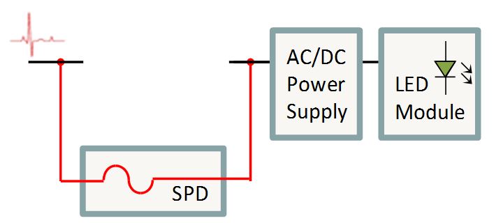
Extracted from Littelfuse_Varistor_LSP05_LSP10_Surge_Protection_Modules_Flyer.pdf
Summary
The high energy savings offered by LED technology enhance the value of outdoor lighting. In order to help LED lighting fixtures reach their expected lifetime, a surge protection module should be added to outdoor LED lighting to prevent premature failure due to lightning surge events and other power line surges.
A surge protection module, installed in front of the LED power supply unit, provides effective protection for lighting systems. However, it may be subject to temporary overvoltage threats and fatigue due to multiple surge events. Thermal disconnects placed in surge protection modules enhance the overall safety of the modules and help them to achieve UL 1449 and IEC 61643-11 certification.
When surge protection modules reach their end-of-life, a mechanism is needed to indicate that the modules require replacement. The series-connected SPD module provides the simplest way of indicating the need for replacement by disconnecting the light fixture from the power source, resulting in the light turning off. Parallel connected SPD modules provide the option to interface with LEDs to indicate whether the modules are online or offline.
The initial cost of installing outdoor LED lighting can be substantial; payback depends on the system surviving long enough to reap the benefits of the lower wattage demand, lower maintenance cost and longer lifetime LED lighting offers. Download the LED Lighting SPD Module Design and Installation Guide.


