


Wideband mixers have many applications in multifunction wireless transceivers, microwave transceivers, microwave backhaul, radar, and test equipment. A mixer with wide bandwidth allows a single mixer to be used in radio architectures with on-the-fly programmability of various radio parameters.
The advanced silicon-based technologies such as CMOS and BiCMOS have demonstrated the capability for high performance mixers in relatively narrow-band applications. It is highly desirable to have broadband mixers that can be made with lumped elements or other structures compatible with IC fabrication techniques and geometries. Balanced mixers are the preferred topology because of their better overall performance compared to unbalanced mixers with respect to linearity, noise figure, and port-to-port isolation. Baluns are critical components used in single-balanced mixers and double-balanced mixers to convert RF, LO, and IF signals between balanced and unbalanced configurations. It is critical to realise baluns can be integrated in standard IC foundry processes so that broadband integrated mixers can be produced.
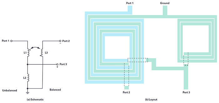
Above: Figure 1. Ruthroff-style broadband balun
In this article, an innovative balun structure that can be easily implemented in silicon, GaAs, or any other integrated process is introduced. This balun topology exhibits much wider bandwidth than a traditional balun structure. A 3GHz to 20GHz high performance mixer is designed using the wideband balun in a 0.18μm SiGe BiCMOS process.
Wideband Balun
The most important performance parameters for a mixer include the conversion gain, linearity, noise figure, and operating bandwidth. The baluns used in integrated mixers have significant impact to all these mixers’ performances. The critical performance of an integrated balun includes operating frequency range, insertion loss, amplitude/phase balance, common-mode rejection ratio (CMRR), and physical size.
Two popular balun structures in the integrated circuits applications are traditional planar-transformer baluns and Marchand baluns. Both of these baluns have good performance for narrow-band applications. The planar-transformer balun consists of two closely coupled transformers. The self-inductance and the resonant frequency of the inductors are two main bandwidth limiting factors. The self-inductance limits the bandwidth in the lower frequency end, and parasitic capacitance and asymmetry termination on the unbalanced and balanced terminals limit the high frequency end.
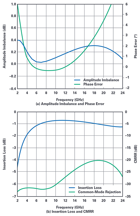
Above: Figure 2. Simulated performance of the broadband balun
The Marchand balun consists of four quarter wave transmission lines and usually needs large real estate on the chip. Miniature Marchand baluns have been demonstrated using interleave transformer layout in integrated circuits. The bandwidth of Marchand baluns is limited by the requirement of the electrical length of each line segment. When the electrical length is farther away from the required quarter wavelength, the amplitude and phase balance are degraded. In general, a well-designed transformer balun or Marchand balun can cover a frequency range of 3× to 4× maximum to minimum frequency ratio with reasonable performance.
It is well-known that the Ruthroff balun exhibits very wide bandwidth and many discrete component products have been developed based on the Ruthroff structure. However, no application of a similar structure for a microwave integrated circuit is found.
Figure 1a shows a Ruthroff-style broadband balun schematic that can be easily constructed in a planar semiconductor process using three inductors. One layout example is shown in Figure 1b. In that layout, only two metal layers are needed, with one thick metal layer for three low loss inductors and an underpass metal layer for connections. When additional thick metal layers are available, the L1 and L3 can be vertically coupled, which results in smaller size and possibly better magnetic coupling between them.
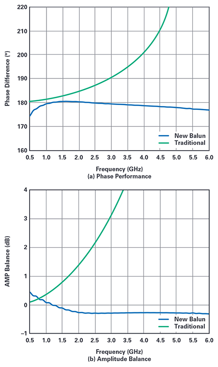
Above: Figure 3. Simulated performance comparison of a traditional balun vs. a new balun
The broadband feature benefits from the simplicity of the structure, which results in less parasitic capacitance. The single-ended signal is voltage divided by L1 and L2. As a result, the positive port of the balun is directly half of the voltage of the single-ended signal with the same phase. The negative port of the balun is half of the voltage of the single-ended signal with 180° phase shift due to the negative coupling between L1 and L3.
Excellent amplitude and phase balance over a very wide bandwidth can be achieved. Figure 2 shows the simulated performance of a broadband balun configuration. The amplitude imbalance is the difference between S21 and S31, and the phase error is the phase difference of S21 and S31 away from the desired 180°. The proposed balun has very good amplitude balance and phase difference of close to 180° between 3GHz and 20GHz. Common-mode rejection is important for a balun to be used in many applications such as balanced mixers and push-pull amplifiers. The simulated results shown in Figure 5b demonstrate that the 3-inductor balun has better than 20dB CMRR over the 3GHz to 20GHz range.
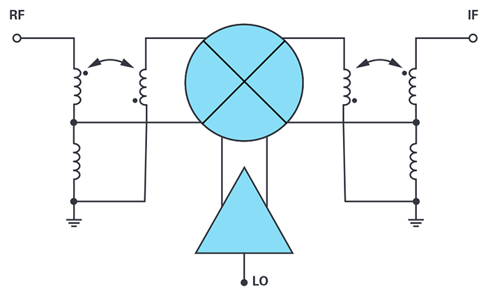
Above: Figure 4. Broadband double-balanced passive mixer
Like the transformer balun topology, the bandwidth of the 3-inductor balun is limited by the inductance at the low frequency end and by the parasitic capacitance at the high frequency end. When the inductance is lower, the load impedance will have more impact to the voltage division between L1 and L2 for port 3 and the transformed voltage for port 2. Although the amplitude balance and phase difference are still acceptable at a low frequency range, the insertion loss is increased. As a result, lower terminal impedance or higher inductance will benefit the low frequency performance. At the high frequency end, the parasitic capacitance between L1 and L2 will degrade the transformer’s performance and results in large phase errors. Careful layout with the consideration of less parasitic capacitance can extend the balun’s high frequency range.
The physical size of an integrated balun limits the low end of bandwidth. To explore the feasibility of the proposed balun structure for lower frequency applications, a 0.5GHz to 6GHz balun is designed and compared with a traditional transformer-based balun, and the performance is shown in Figure 3.
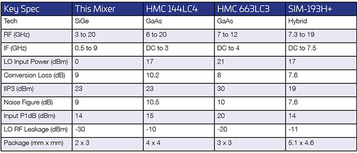
Above: Table 1. Comparison of ADI Broadband mixer and similar products on the market
Integrated Broadband RF/microwave mixer
A broadband double-balanced passive mixer has been designed in Jazz’s SiGe 0.18μm process with the 3-inductor balun configuration. The RF, IF, and LO ports of the mixer are 50Ω single-ended with baluns integrated for the RF and IF ports. The integrated RF balun is optimised to cover the 3GHz to 20GHz RF frequency range. The integrated IF balun is optimised to cover a very wide, 500MHz to 9GHz, frequency range. The single-ended LO signal is converted to a differential signal internally by an active amplifier circuit to reduce chip size. Two stage broadband amplifiers using high speed NPNs provide enough signal voltage swing to the MOSFET gates of the passive mixer with only 0dBm input power over the 1GHz to 20GHz frequency range.
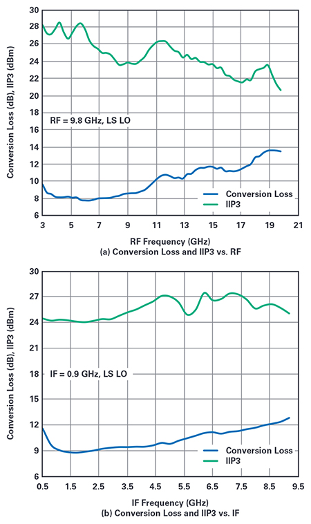
Above: Figure 5. Measured performance of the broadband double balanced passive mixer
The mixer is packaged in a tiny 2mm × 3mm QFN with flipchip using copper pillars for the interconnections. The copper pillar connection has very low additional parasitics to preserve the broadband performance from the silicon. The mixer is biased with 3.3V supply, and the current consumption is 132mA at room temperature. The measured conversion loss and IIP3 performance is shown in Figure 5. The mixer’s RF, LO, and IF ports are well matched over its wide operating frequency range. Figure 6 shows the return loss of these ports. It should be noted that the RF return loss is dependent on the IF port impedance, and the results in Figure 6a are measured with an IF frequency of 0.9GHz.
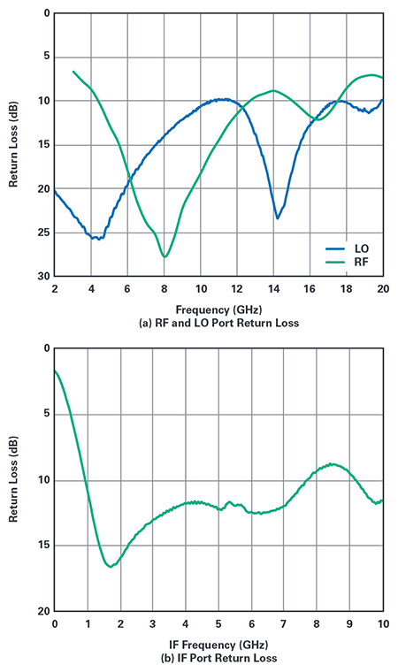
Above: Figure 6. Measured return loss of the broadband double balanced passive mixer
Compared with broadband mixers on the market (such as those in Table 1), the mixer designed with the 3-inductor baluns achieves the widest bandwidth for both the RF and IF range. It requires the lowest LO power with the highest integration level. The overall performance is superior than any reported product or published broadband mixer product.