

Of course, real-world measurements will have real-world errors. Even if the errors are small on their own, the error will build over time. And combining data with dead reckoning can exacerbate these errors – and the estimate of the robot’s position will become increasingly inaccurate.
How can robot designers minimise the impact of these errors, and achieve the best possible accuracy? There are three main types of positional sensors used in this kind of application: the next sections look at them one by one to understand where these errors come from.
Wheel encoders
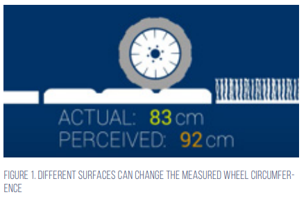
First off, the rotation of the robot’s wheels is measured using wheel encoders. One way to achieve this method of measurement is to use a simple LED and photo sensor to detect evenly-spaced holes in a rotating disk attached to a wheel. Alternatively, magnets can easily be used to detect and measure the rotation. By knowing the wheel circumference and the position of the wheel encoder sensors, a robot can calculate how far it has moved.
On some surfaces like dirty floors, thick carpet, and over flooring transitions, wheels can easily slip or skid. This causes the wheel encoder’s perceived distances to be different from reality (see Figure 1).
Inertial measurement unit sensors The robot’s relative heading can be calculated from the wheel encoders but, as we’ve seen, this can be inaccurate. A better option is to use an inertial measurement unit (or IMU). This sensor is comprised of an accelerometer and gyroscope, and possibly also a magnetometer, which collectively enable it to measure its linear acceleration, angular velocity, and magnetic fields (including an estimation of the Earth’s magnetic field), respectively.
When comparing inertial sensors, there are multiple factors to consider. Of these, the most influential in terms of sensor accuracy are gyroscope scale, gyroscope bias (also called zero rate offset, or ZRO), and accelerometer bias (also called zero gravity offset, or ZGO).
Gyroscope scale is a multiplicative error in the gyroscope output relative to its motion. For instance, if there was a scale error of 1%, then the gyroscope will be one degree off for every 100 degrees travelled (101° or 99°). This impacts any ground-roving robot by influencing the heading that it believes it is travelling by that same amount.
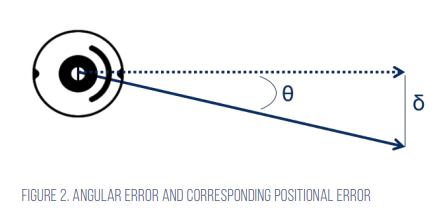
Gyroscope bias is the angular rate measured by a sensor while it is at rest. Given that angular position is determined as the integral of angular rate, any offset error leads to an ever-growing heading error. Any angular error is extended along the robot’s path, creating a growing positional error (Figure 2).
Accelerometer bias is a similar principle to gyroscope bias. It is the acceleration measured while the device is motionless (ideally equal to gravity). Accelerometer output offsets result in pitch and roll errors. These offsets can affect overall orientation calculations and, in the case of a magnetometer, tilt compensation.
Optical flow sensors
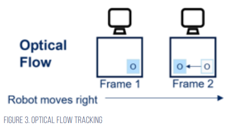
The third sensor type to consider is the optical flow sensor, which is the same technology as that used in a computer mouse: it illuminates the floor, detects tiny features on the surface, and measures their movement between frames (Figure 3)
This means that the sensor can track robot movement independent of any errors due to wheel slippage. On the other hand, the perceived motion of a feature is a function of both velocity and of the distance between floor and sensor. If this distance is not precisely calibrated, or if it varies during use, measurement accuracy will decrease.
Optical flow measurements can also be affected by the floor surface type, as very smooth or dark floors may not have enough visible features for reliable tracking.
Three is the magic number
With these three types of sensor, a robot can combine and compare the data that it is capturing from multiple sources to give the best accuracy. For example, operators can compare the distance estimates derived from the wheel encoder and IMU sensors to cross-calibrate the scale of optical flow measurements while in operation.
Once the optical flow is calibrated, operators can continue to use filtered measurements from each sensor to estimate the quality of data from the IMU and wheel encoders. Continually comparing and updating each sensor’s data with one another eliminates the need for factory calibration and allows the system to adapt to changing operating conditions. These quality estimates are important for determining when to trust data from sensors that are performing well and when to reject data from sensors that aren’t.
Suitable algorithms are required to combine, calibrate and analyse all this data, and to handle the complexity of multiple sensors. For example, CEVA’s MotionEngine Scout software processes the data from wheel encoders, an optical flow sensor, and an IMU – to give much higher accuracy than could be achieved by one type of sensor.
This fusion from Scout also cross-calibrates each sensor using information from the others, and it also simplifies the complexities of working with various sensors with a single end interface. By providing OEMs with a simple interface for their robot navigation, developers and manufacturers can develop products that work with precision to meet end users’ objectives.