


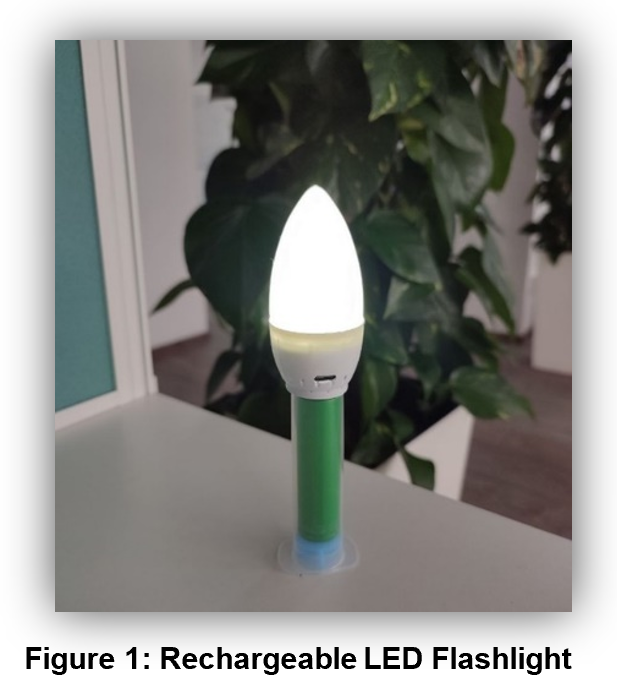
In this article Irena Zhuravchak, Technical Documentation Apps Engineer, Renesas Electronics, Lviv, Ukraine, describes how to create a rechargeable LED flashlight using the HVPAKTM SLG47105V.
The device has a powerful flashlight and a strobe mode. This mode is useful in tactical situations to temporarily blind an attacker or in situations to urgently signal for attention. The flashlight is powered by a 3.7V Li-ion battery that is charged with Constant Current (CC) – Constant Voltage (CV) control circuit.
The design is created in Go Configure Software Hub | Renesas. The complete design file can be found at AN-CM-367 Rechargeable LED Flashlight. More ideas on using the HVPAK SLG47105V you can find at the Renesas website.
1. Construction and Operating Principle
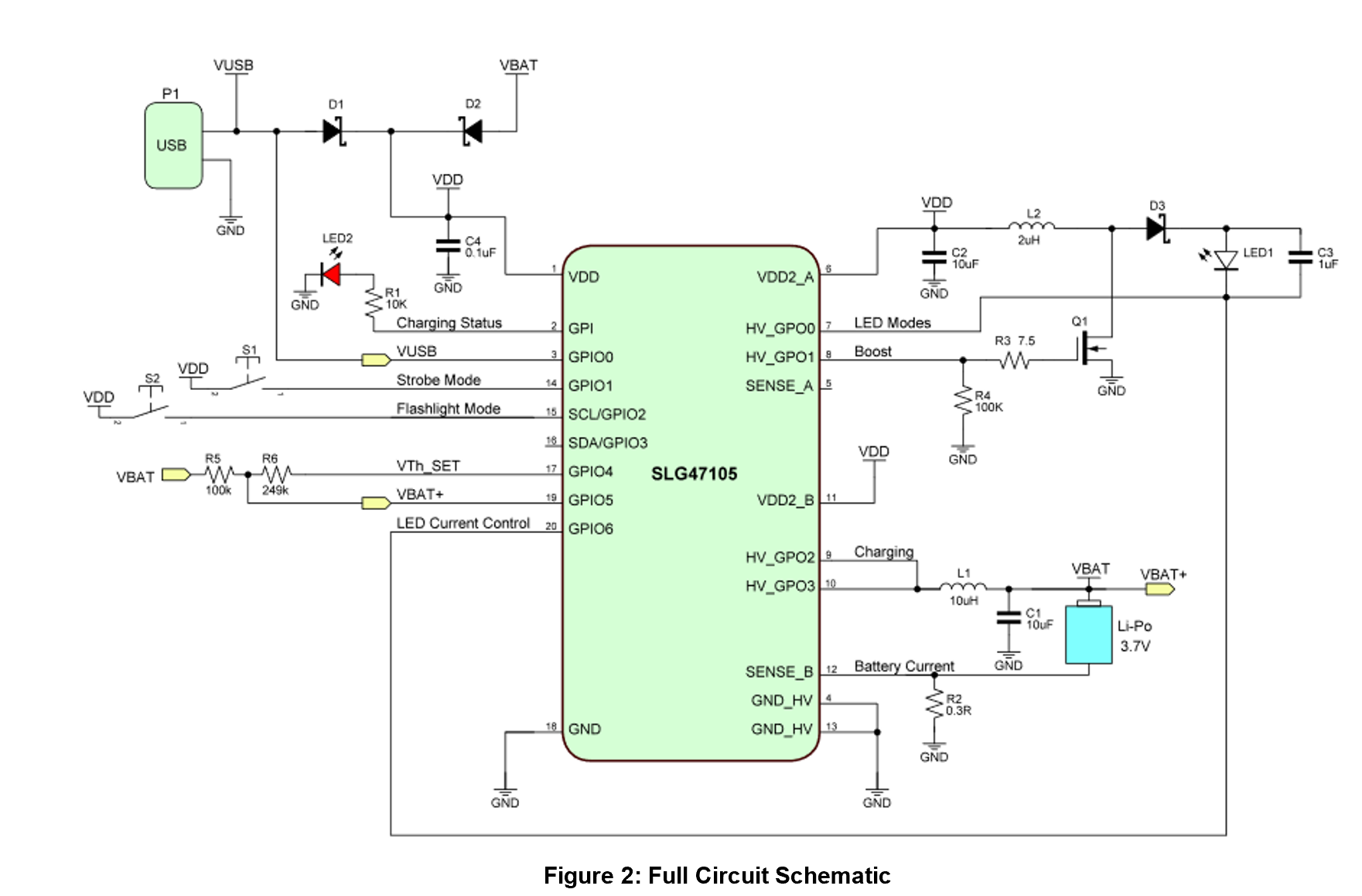
The Full Circuit Schematic is shown in Figure 2.
As can be seen in Figure 1, the LED flashlight contains two modes – flashlight mode and strobe mode. These modes are selected by two push buttons S1 and S2.
The circuit is powered by a Li-ion battery, so the VDD is between 3.0V and 4.2V. The LED intensity depends on voltage VDD, so the DC/DC Boost Converter is added to provide the constant necessary current to the LED.
2. GreenPAK Design
The GreenPAK Design consists of two parts LED Control and CCCV Battery Charger.
2.1 LED Control
The LED Control part is shown in Figure 3.
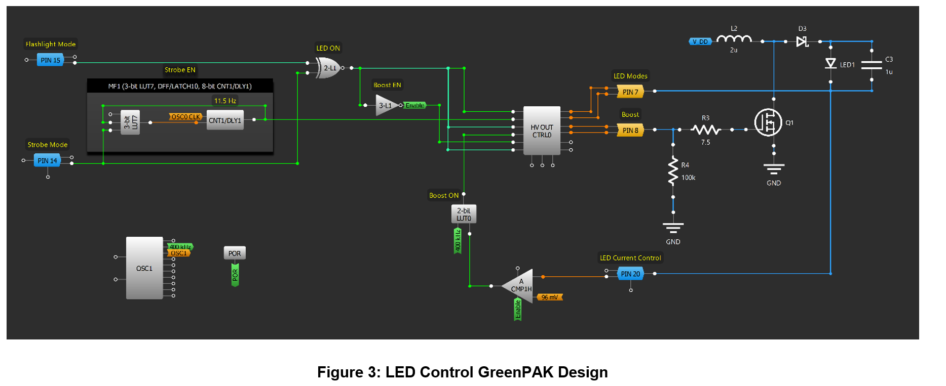
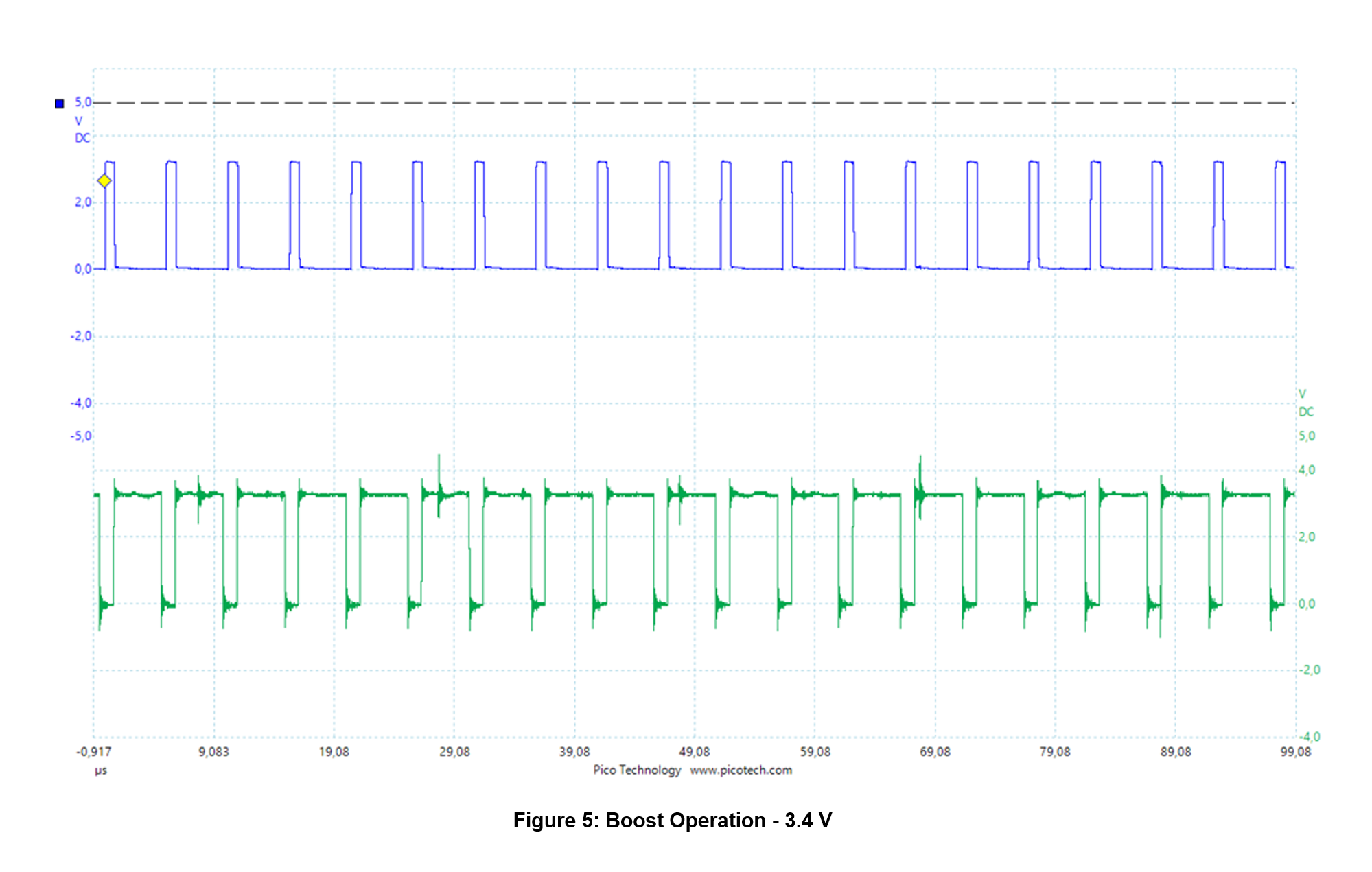
The 400kHz signal with a 50% duty cycle is created by OSC1 and goes to the 2-bit LUT0, which controls the Booster circuit through the HV PIN 8. 2-bit LUT1 selects the needed mode, then 3-bit LUT1 enables the Boost circuit (OE1). When the maximum LED current of 700mA is reached (Vref = 96mV, PIN7 Rsense ~ 150mΩ), the ACMP1H sets the LUT0 to 0 and pulls down the HV PIN 8 keeping the current through the LED at the same level.
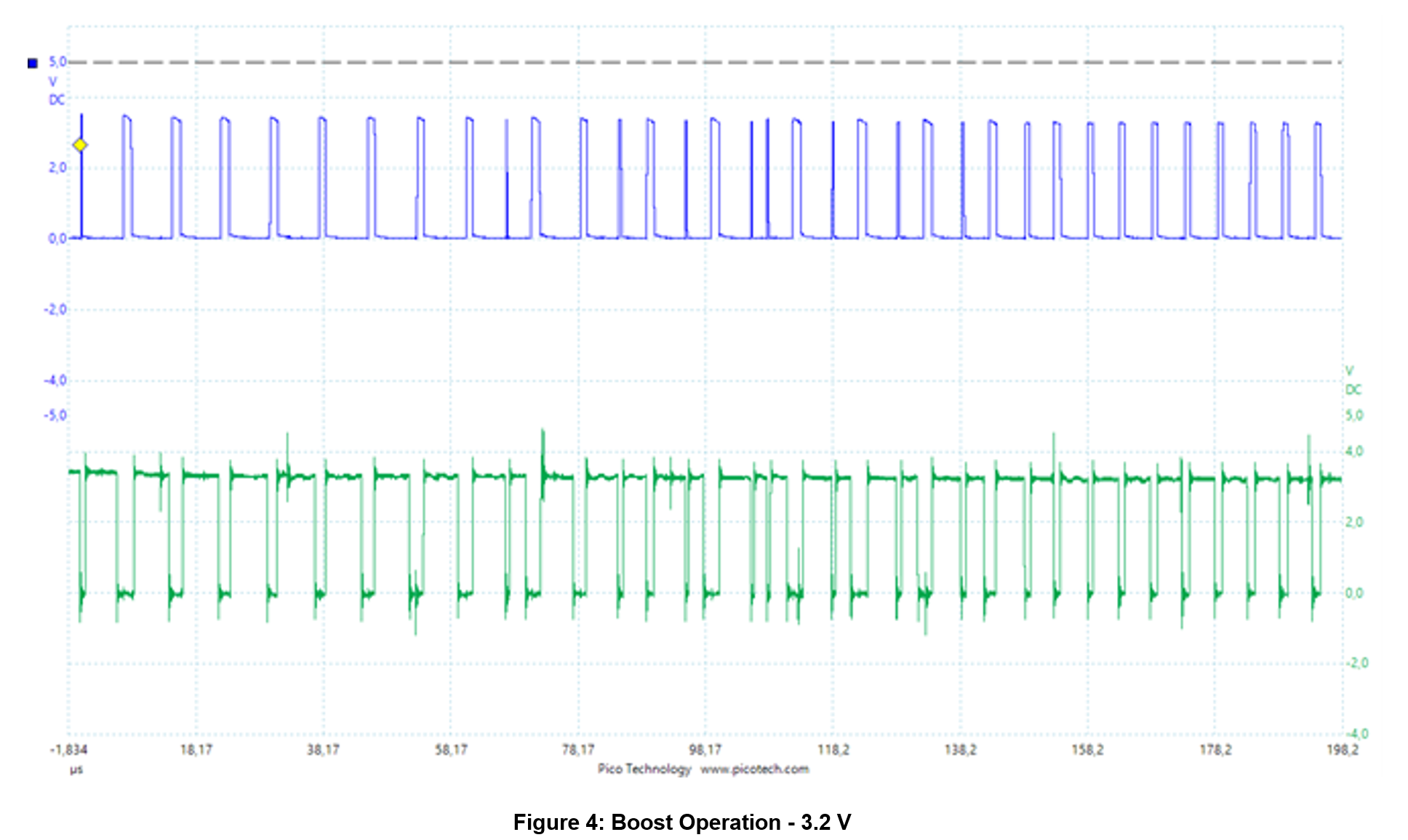
It should be noted that the external MOSFET must be selected with the lowest possible gate threshold voltage and high enough current. For example, IRL3303.The results of Boost can be found in Figure 2 and Figure 5. The HV PIN 8 is represented in blue and the ACMP1H is in green.
The necessary LED mode is selected by 2-bit LUT1 and MF1 (DFF10). These signals go to HV PIN 7 of the HV OUT CTRL0 which is configured as a Half-Bridge and acts as a switch for the LED. So, the LED is ON when PIN 7 is LOW and vice versa. Also, the internal low-side MOSFET (PIN 7) is used as a current sensor. Its RDS On is about 150 mOhm which is perfect for our purpose.
Strobe Mode
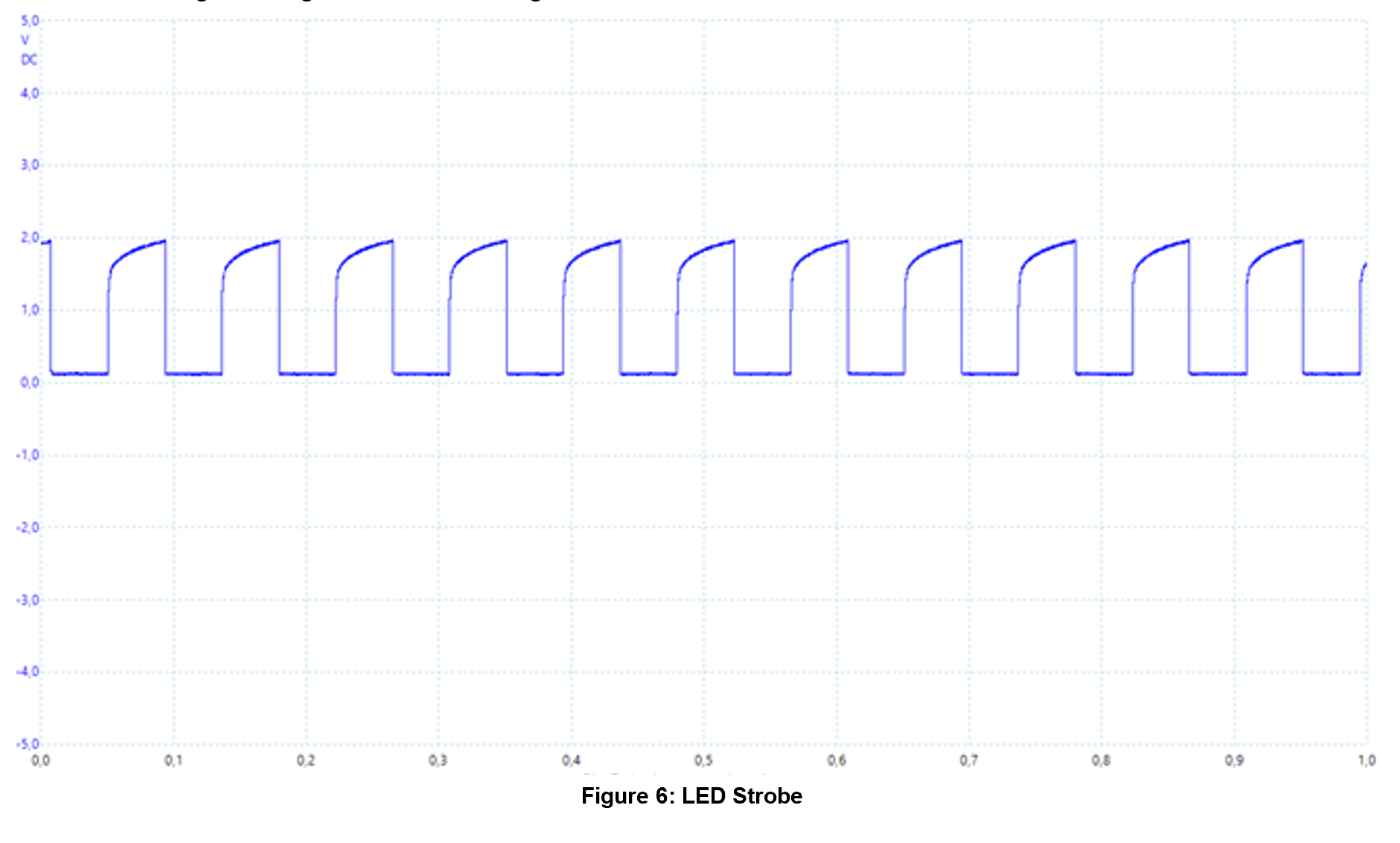
In the LED strobe light mode, the 3W LED is connected to PIN 7 of HV OUT CTRL0 with an input of 11.65Hz. The resulting LED signal is shown in Figure 6.
Flashlight Mode
In the flashlight mode, the DFF10 sets the Enable signal OE0 of the HV OUT CNTR0 to HIGH, and the 2-bit LUT1 set the IN0 to LOW, so the output of PIN 7 is continuously LOW, and the LED is continuously ON.
2.2 CCCV BatteryCharger
The CCCV Battery Charger GreenPAK Design is shown in Figure 7. To get more information please see AN-CM-363 CCCV Battery Charger GreenPAK Design File.
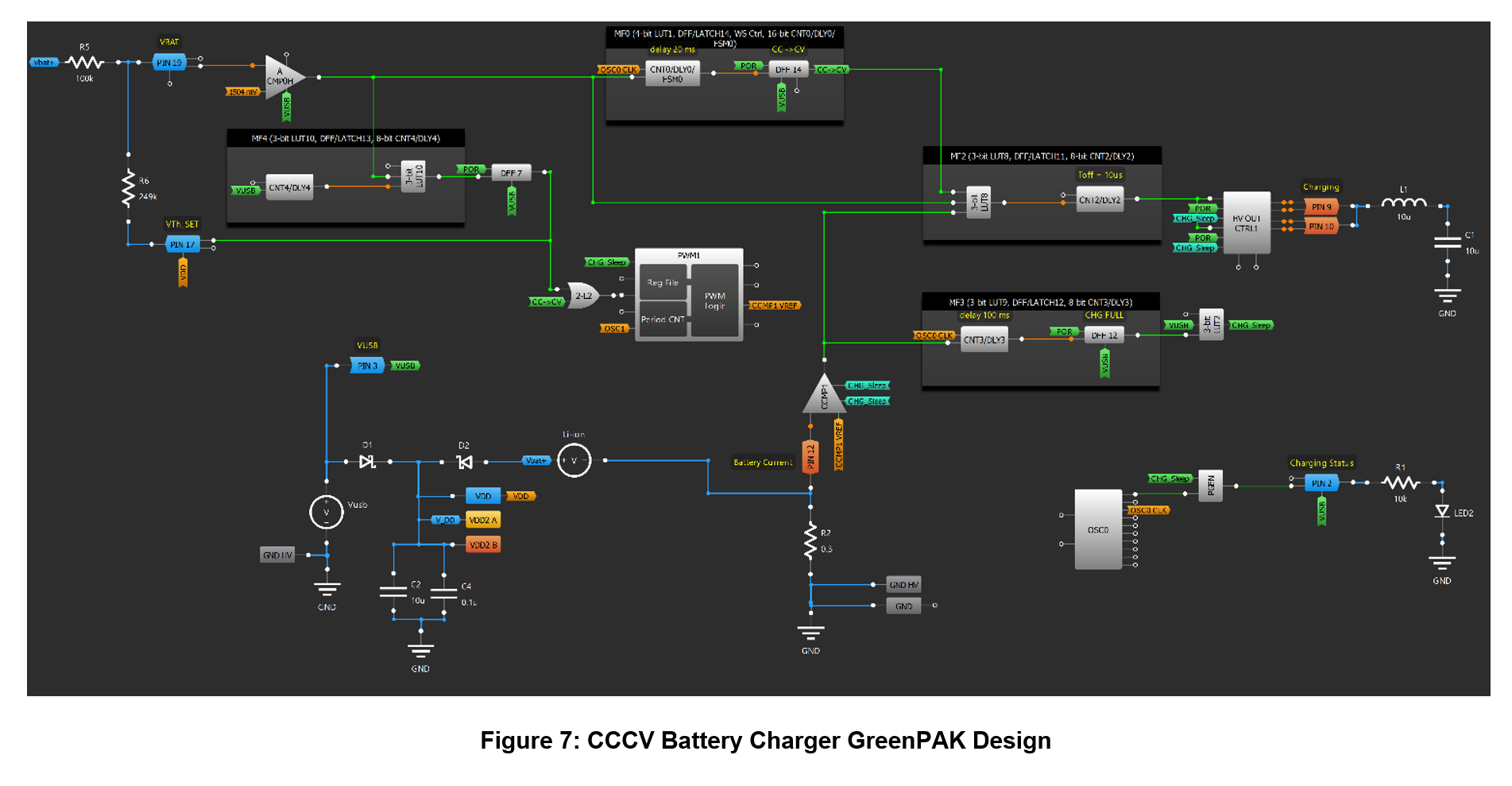
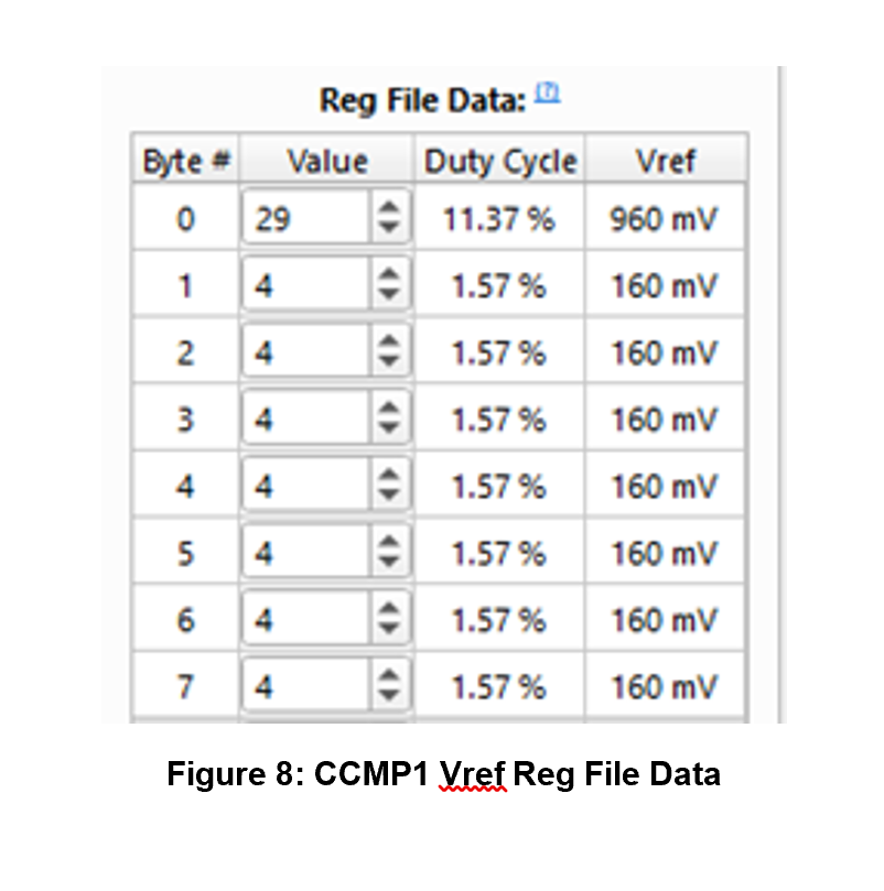
If the Vusb is connected, PIN3 detects it and powers ON the ACMP0H. The ACMP0H checks the Vbat voltage. DFF7’s output is HIGH, so no voltage divider is connected to PIN19. If Vbat is lower than 3V the Pre-charging stage starts. PWM1 sets the current and CCMP1 controls it (IN+ Source with x8 gain of the CCMP1). In this case, the Up/Down input of the PWM1 macrocell is LOW, which means that we start charging from Vref = 160mV for CCMP1 Vref (Figure 8). As a result, the CCMP1 maintains the 67mA current:

As soon as the ACMP0H output is HIGH (the Vbat is higher than 3.0V), the DFF7 output goes to LOW and the voltage divider is connected to PIN19. The Constant Current phase starts. In this case, the ACMP0H makes a comparison for 4.2V (not 3.0V as in 1st case). The Up/Down input of the PWM1 is HIGH, so the CCMP1 Vref is 960mV. The resulting current is ~ 400mA. Note that these current limits can be changed by changing the Vref value in the Reg File or by changing the resistor connected to the PIN 12 (Sense B).
This CC phase continues until the battery voltage reaches 4.2V (ACMP0H output is HIGH). Then the Constant Current stops and the Constant Voltage phase starts. The Up/Down input of the PWM1 is LOW, so the CCMP1 Vref is 160mV. In this case, the ACMP0H controls the constant voltage of 4.2V, and the CCMP1 just checks and keeps the current decreasing and lower than the battery full current (IBF) of 67mA until the battery is fully charged. When the battery is fully charged, the charging process stops, and all corresponding blocks are in Sleep Mode (CHG_Sleep is HIGH).
Conclusion
We have described how to configure the HVPAK to create a rechargeable LED flashlight. The device has two modes – flashlight and strobe light. The results prove that the circuit works as expected, and the HVPAK is capable of acting as the control module for the powerful LED and 3.7V Li-ion battery charger at the same time.
The GreenPAK’s internal resources, including the HV, oscillators, logic, and GPIOs are easy to configure to implement the desired functionality for this design.