


This article describes the development of in-wheel motors, and outlines some of the design integration issues such as drive electronics
In-wheel motors: an approach reinvented for EV drivetrains
Automotive development has always been a conservative, evolutionary process and even with the profound technology change in EVs, designers have ‘played it safe’ as far as possible, wanting to keep the general layout, shape and feel of an EV as similar as possible to a conventional ICE powered vehicle.
Because of this approach, EV designs so far have tended to replace the petrol or diesel engine with a single electric motor coupled through a traditional arrangement of driveshafts, differential gearbox and, for front wheel drive, constant velocity joints. Designs with multiple motors do exist but these still are generally fixed within the vehicle chassis, with mechanical couplings to the wheels.
In the late 19th century, Ferdinand Porsche had a better idea; he developed a ‘horseless carriage’ in the form of the ‘Lohner-Porsche Electromobile’ (Figure 1), that had an electric motor embedded in each wheel hub, powered by batteries, in turn charged by an on-board petrol engine.
Control of the motors was rudimentary but the power losses in the conventional powertrain and gearbox of an ICE were eliminated. The steering was hugely heavy, power was low and with its one-and-a-half-ton weight, range was poor. So, the car disappeared into history as an automotive oddity.
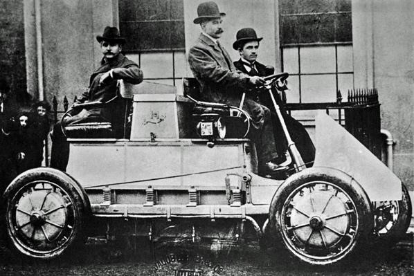
Figure 1: The Lohner-Porsche Electromobile with hub electric motors.
The idea of hub electric motors has resurfaced however, notably in the Lunar Roving Vehicle (LRV) in the early 1970s, but more recently in practical implementations for road-going cars. Sometimes dubbed ‘active wheel’ technology, Michelin were pioneers of the technique in the late 2000s and active development has continued to today with concept demonstrators such as the Nissan ‘BladeGlider’ showing that it can be a practical reality.
How in-wheel motors score
Up to four hub-motors would seem to be more complication compared with a single chassis-mounted unit, but when a system-wide view is taken, there are real advantages: direct drive to the wheels eliminates drivetrain losses from a centralised electric motor, with a mechanical differential now being unnecessary and overall weight can be lower. One company working on the development of hub drive systems claims that the overall weight and energy savings can yield more than 30% improvement in range, depending on battery size and driving cycle.
Hub motors can be extremely compact and together with removal of the driveshafts and differential, cabin space is potentially enlarged and more flexible. If the drive electronics are also integrated, wiring is simplified – just a single power line and return rather than at least three power cables to each motor that would be necessary if the traction drive inverter was chassis-mounted. Keeping the variable frequency drive to the motor within the hub also reduces electromagnetic emissions from cables.
A major advantage is the possibility to improve driving dynamics and safety; in a conventional ICE, complex mechanical arrangements are used to provide anti-lock braking and traction control to avoid wheel slip on poor surfaces and when cornering. A differential gear also allows wheels to rotate at different rates while cornering to reduce tyre wear and improve handling, with some advanced arrangements such as ‘limited slip’ for off-road use.
These systems can be extremely complex, with electronics sensing demanded and actual wheel speed and torque, but ultimately, the only control available is to increase or throttle back the entire engine power or apply braking to individual wheels.
With a single fixed electric motor all this mechanical and electrical complexity must remain, although unlike an ICE, the motor can reverse its torque for overall braking effect. Hub motors however can be individually controlled for torque, target wheel speed and braking, reacting to sensors on each wheel and driver inputs. So-called ‘torque vectoring’ can apply power to each wheel separately for optimum handling and safety (Figure 2).
Although the hub motor can achieve a braking effect by regeneratively converting wheel rotation energy to battery charge and by reversing its torque, hydraulic/friction brakes are still present to avoid overloading the motor drive under heavy braking.
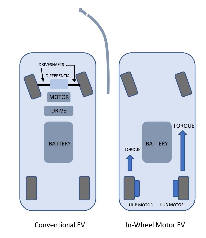
Figure 2: Hub motors can implement torque vectoring simply.
Hub motors have perceived down-sides however, multiple motors are needed, each with its own electronic drive, with a combined cost that is higher than a single motor for the same power output. It can be argued though that energy savings would eventually provide payback and the other safety and performance advantages, along with extra cabin space and range, have an offsetting value as well.
There are also practical problems – a hub motor is now part of the ‘unsprung weight’ of the vehicle, that is, components not supported by the suspension. This surely affects handling, but tests have shown that the effect is not disruptive in normal driving up to certain weight limits. The hub motor, electronic drive and mechanical components are also in a more severe environment compared with a single motor that is enclosed within the chassis and cushioned by coil suspension and dampers.
The tough environment
Unsprung components in a vehicle are in perhaps the worst of all situations, hammered by road shocks and vibration, pelted by road debris and open to the corrosive elements of water and salt from road treatment. Adjacent friction brakes can glow red hot and, efficient as they are, a hub motor and its drive electronics also generate significant heat.
To maintain long life and reliable operation, the hub motor and its components must be extremely robust – failure that results in lock-up or even sudden loss of traction could be fatal. Automotive quality standards of course apply, ISO 26262, for functional safety and systems must achieve Automotive Safety Integrity Level (ASIL) D, the highest category. Individual components must be certified appropriately, AEC-Qxx for passive and active electronics from automotive-qualified suppliers meeting ISO/TS 16949 quality standards for design and manufacturing with a Production Part Approval Process (PPAP).
Drive electronics
While advances in technology have led to smaller motors, the drive electronics are also a size and weight factor when embedded in a hub. Traction motors used are mostly permanent magnet, synchronous (PMSM) types that require a three-phase variable frequency drive implemented by a ‘bridge’ arrangement of semiconductor switches, under pulse width modulation (PWM) control.
The bridge is switched at high frequency with an output effective amplitude set by pulse width, representing torque demand (Figure 3).
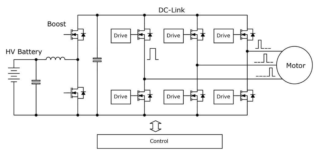
Figure 3: EV electric motor drive using MOSFETs.
Following the usual conservative approach, EV designs have so far predominantly used IGBTs as switches, a technology first proposed in the 1960s, which, although it has been refined over the years, limits bridge PWM clock speed for reasonable efficiency, due to losses incurred as the device switches – higher frequency equals more transitions per second, incurring more losses.
Motor drives, particularly at high power, often switch at less than 10kHz for this reason, producing relatively high ripple voltages and currents, compromised motor control response and differential and common mode interference currents that are difficult to filter. The limited efficiency achievable also reads across to larger heatsinking necessary and its consequent, prohibitive weight in a hub motor drive.
To achieve faster switching with its control and EMI benefits, while also increasing efficiency and consequently reducing volume and weight, new semiconductor switch technologies are being adopted for hub motors. Silicon Carbide MOSFETs are a typical choice – being a wide band-gap device, conduction losses are low, operating temperature is high and the device can switch extremely quickly with minimal loss, allowing PWM frequencies at tens of kHz.
SiC can switch at MHz rates but in motor control, this gives no significant benefit, unlike in general power supply applications, where transformer size would reduce considerably. A feature of motor control bridge circuits is that ‘commutation’ occurs – current flows in the reverse direction to normal during switch ‘dead’ time and during regeneration, so to allow this, a fast, parallel diode has to be added to IGBTs.
For SiC MOSFETs however, there is an integral ‘body’ diode which can perform the function, although for the highest efficiency, this may be bypassed by an external diode. SiC MOSFETs are available with appropriate voltage and current ratings for the highest proposed battery voltages and hub power levels, currently around 80kW. With a single chassis mounted motor, the electronic drive must supply the full vehicle power, perhaps hundreds of kW, so the choice between IGBTs and SiC MOSFETs is not as clear cut, with IGBTs more commonly available at highest current ratings.
Automotive-grade SiC MOSFETS, IGBTs and other active components from suppliers such as Infineon, STMicroelectronics, Texas Instruments, and Wolfspeed Cree, along with a large portfolio of passive and electro-mechanical components, can be chosen from ranges supplied by Mouser Electronics.
Summary
Hub electric motors in EVs have a distinguished heritage and with advances in motor and drive technology, they have become viable alternatives to the chassis-mounted motor approach, while promising advantages in fuel economy, range and driving experience. With the upcoming move to autonomous vehicles, the cabin space savings match-in with the goal of making the vehicle more of a ‘mobile room’ to work and relax in.