
Discrete linear pre-regulator for automotive rear lights
LED-based lighting is increasingly popular in automotive applications like headlights and rear lights. These applications use an LED driver circuit, with the goal to maintain constant current. LEDs in modern automotive rear lights generally require current below 150mA which, given electromagnetic interference (EMI) and cost considerations, has made a linear LED driver a more appealing solution than a switching regulator. Michael Helmlinger, Systems Engineer, Marcoo Zamora, Applications Engineer and Olivier Mellin, Field Application Engineer at Texas Instruments (TI) explain.
Good thermal design is always critical for linear LED drivers - particularly for systems where the total LED current exceeds 100mA or have an input-to-output voltage drop above 5V. Such systems are typically found in automotive stoplights and tail lights, animated stoplights and tail lights, and turn indicators where thermal constraints pose a challenge.
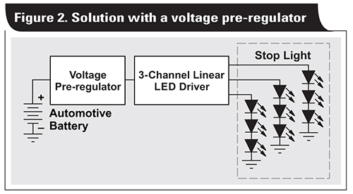
One way to address the thermal challenges of singlestage linear LED drivers is to add a voltage pre-regulation stage. Using a wide input voltage (VIN) low-dropout regulator (LDO) is the natural choice for pre-regulation, but even a wide-VIN LDO may not be able to dissipate the heat generated over the full automotive temperature range, especially if multiple linear LED drivers share the preregulation stage.
A discrete solution using the TL431LI-Q1 for the regulation and multiple bipolar junction transistors (BJTs) in parallel for heat dissipation enables the design of a high power and cost-efficient discrete linear pre-regulator. This article describes how to design the circuit of this linear regulator for specific needs and common challenges.
Automotive LED drivers
Automotive LED driver solutions vary, mostly with the LED topology (the number of LEDs stacked in series) and the driving current: the application’s required lumen output usually governs both. Current for modern red LEDs in tail lights and stoplights is set to a maximum of 100mA.
Maximising the number of LEDs stacked in series reduces the voltage across the linear LED driver, the thermal dissipation in the LED drivers and the overall LED current, since it is not necessary to drive as many LED strings in parallel. In automotive applications, the nominal input voltage is the battery voltage (13.5V nominal) and it goes down to 9V, which limits the number of LEDs in series to usually three.
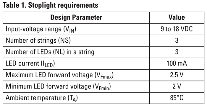
Table 1 (above) lists example requirements for a stoplight.
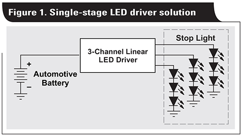
A design with a single-stage linear LED driver without a voltage pre-regulator, as shown in Figure 1, would lead to the calculation shown in Equation 1 for the worst-case power dissipation:
![]()
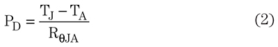
A modern linear LED driver like the TPS92630-Q1 has a JEDEC junction-to-ambient thermal resistance (RθJA) of 41.5°C/W with a maximum operating junction temperature (TJ) of 150°C. Real-life RθJA obtained on printed circuit boards (PCBs) will be lower, so the JEDEC EIA/JESD51-x series of documents lists a good worst-case value to use for calculations. With a thermal resistance of 41.5°C/W, the maximum power dissipation of the linear LED driver must be 1.6W in order to stay below the maximum TJ of 150°C when TA is 85°C, based on Equation 2:
A 3.6W requirement (from Equation 1) severely limits the maximum TA of the linear LED driver, which will not work well in automotive applications required to sustain a minimum TA of 85°C. Adding a voltage pre-regulator, as shown in Figure 2, spreads the power dissipation between the pre-regulator and the LED driver.
Discrete high-power and cost-efficient discrete linear pre-regulator
Figure 3 shows a linear voltage preregulator schematic based on the power requirements listed in Table 1. The circuit consists of a TL431LI-Q1 voltage reference (U1), N-channel P-channel N-channel (NPN) transistors (Q1-Q3), a feedback resistor network (R5, R8) and input/output capacitors (C1, C2). This linear preregulator is designed to support a maximum LED string forward voltage of 7.5V with an LED driver dropout voltage of 0.5V. The preregulator output voltage is set to 8V with a maximum load current of 300mA.
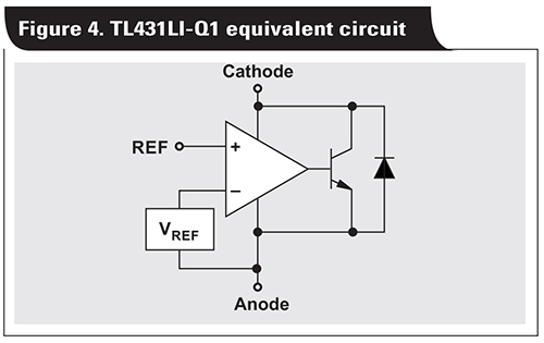
The TL431LI-Q1 combines a voltage reference with an internal error amplifier that enables the device to both provide a voltage reference and regulate its output. Figure 4 shows the equivalent schematic.
The TL431 comes in different variants. Versions ending in LI, such as the TL431LI-Q1, are low-cost and offer improved capacitive load stability and lower bias current. The only difference between the TL431LI-Q1 and TL432LI-Q1 is the pinout. Each device comes with A and B accuracy grades and I and Q operating temperature ranges. Most TL431 devices are also available in automotive grade versions that are designated by the -Q1 suffix; the TL431-Q1 has the largest bias current range in the family.
Passive components
The output voltage in Figure 3 is set to 8V by the resistor feedback divider network of R5 and R8 feeding into the REF pin of the TL431. Placing resistors R1 through R3 on the emitter of the transistor adds negative feedback, which helps balance the current evenly across the transistors.
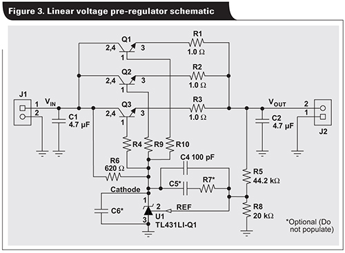
In this linear pre-regulator, R6 limits the bias current of the TL431LI-Q1. R6 has to be a size that keeps the bias current within the recommended operating conditions over the full input voltage range and current load. It is possible to calculate the bias current as the current flowing through R6 minus the BJT’s base current. This design example addresses a maximum input voltage of 18V. To cover higher voltages, including the load-dump voltage, use a constant-current circuit for biasing the TL431-Q1 instead of resistor R6.
Stability
A typical voltage regulator uses a feedback loop to maintain a constant output voltage. As with any feedback loop, the amount of phase shift determines the loop stability. Capacitors impact loop stability by adding a pole in the loop (C2 and C6 in Figure 3). Since each pole contributes 90 degrees of phase shift, the system might require compensation to be stable.
Adding capacitor C6 on the TL431LI-Q1 cathode typically improves immunity to EMI. Capacitor C2 is the output capacitor in this high-power and cost-efficient discrete linear pre-regulator. The larger the output capacitor, the more the design is resilient toward load transients from LEDs turning on and off.
One common way to design for compensation is to increase the series resistance of the capacitor, as described in the application report, ‘Understanding Stability Boundary Conditions Charts in TL431, TL432 Data Sheet.’ [1]
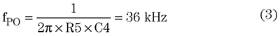
The linear pre-regulator shown in Figure 3 uses a compensation network around the TL431LI-Q1’s internal error amplifier (C4), which places a pole in the origin at a low frequency. C4 reduces the bandwidth of the feedback network of the TL431LI-Q1 and eliminates the effect of high-frequency poles in the system. This type of compensation with a single capacitor is also called dominant pole compensation. The application report ‘AN-1148 Linear Regulators: Theory of Operation and Compensation’ has more details. [2]
Equation 3 calculates the frequency of the pole where the gain plot should cross 0dB. A value of 100pF gives 36kHz:
A type II compensation network can further improve the feedback loop bandwidth of the system by adding a pole and a zero with component C5 and R7.
Pass element
The linear pre-regulator in Figure 3 uses NPN transistors as a pass element. The TL431LI-Q1 and NPN combination requires at least 1V from input to output to stay in regulation. The main advantage of using NPN transistors is their low cost and low output impedance which makes them easy to compensate. NPNs are useful in applications with output currents below 200mA.
Depending on the maximum expected power dissipation, it is possible to calculate the number of parallel transistors based on the package’s thermal dissipation. For example, the SOT-223 package has a balance between cost and thermal performance. The thermal resistance of the SOT-223 package is around 50°C/W on a PCB with 1-oz copper, which follows the JEDEC EIA/JESD51-x series of documents.
One NPN in the SOT-223 package can dissipate about 1.1W at a TA of 85°C while staying below a TJ of 150°C, as calculated by Equation 4:
![]()
Equation 5 calculates the maximum power dissipation of the pre-regulator:
![]()
The linear pre-regulator needs three NPN transistors to dissipate the heat at a TA of 85°C while staying below a TJ of 150°C. For higher power requirements, the number of transistors can be increased.
With the designed voltage pre-regulator in the system, the power dissipation on the LED driver is now only 0.6W, as shown in Equation 6:
![]()
Thermal performance
Figure 5 shows the thermal performance of the linear voltage pre-regulator based on the schematic in Figure 3. The dimension of the two-layer test PCB is 85mm by 40mm and has 1oz copper. The maximum temperature on the NPNs is 80°C at an 18V input and a TA of 25°C. At a TA of 85°C, the maximum temperature stays below the maximum TJ of 150°C.
Bode plot
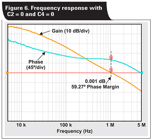
Figure 6 shows the gain and phase of the discrete linear voltage regulator without an output capacitor or compensation network (C2 and C4 not populated). The system is stable with high unity gain bandwidth and a 60 degree phase margin.
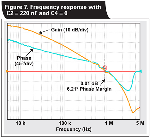
Figure 7 shows the gain and phase for the circuit with an output capacitor C2 of 220nF and without a compensation network (C4). The system is unstable, with only a six degree phase margin.
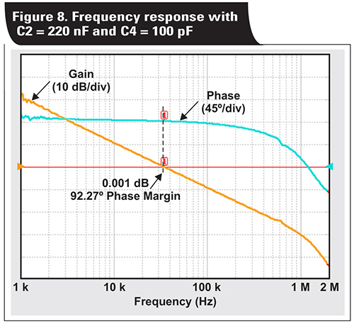
Figure 8 shows the effects of adding a type I compensation network C4 with a 100-pF capacitance. The output capacitor C2 remains, with a value of 220nF. The system is stable, with a crossover frequency of 35kHz and 92 degrees of phase margin.
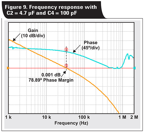
In Figure 9, the output capacitance C2 increases to 4.7µF. The system is still stable with a crossover frequency of 34kHz and a 79 degree phase margin.
Conclusion
Meeting thermal performance in automotive applications with high currents can be a challenge for short-string LED drivers. A discrete linear regulator using the TL431LI-Q1 for automotive applications helps address common design challenges such as power dissipation and stability. By using the TL431LI-Q1 in a linear regulator configuration, it is possible to meet thermal performance for typical automotive applications while retaining a low cost.
References
1. Ronald Michallick, ‘Understanding Stability Boundary Conditions Charts in TL431, TL432 Data Sheet,’ Texas Instruments Application Report (SLVA482A), January 2014.
2. ‘AN-1148 Linear Regulators: Theory of Operation and Compensation,’ Texas Instruments Application Report (SNVA020B), May 2013.

Product Spotlight
APV1111GVY
Panasonic

Panasonic PhotoMOS® Photovoltaic MOSFET High-Power Drivers
| SKU: | |
|---|---|
| Stock: | 3490 |
| Cost: | $3.95 |
