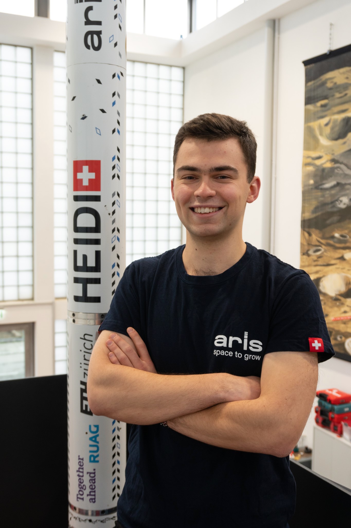


The autonomous recovery system consists of a rocket-shaped tube of about six feet (or 1.8m) and a ram-air parachute with an area of 135 square feet (approximately 13m2). The team guide this parachute by pulling at its steering lines, deflecting the canopy and making turns that way. Guidance happens autonomously, i.e. the trajectory is computed online, taking estimated wind speeds, the current position and the target position into account.
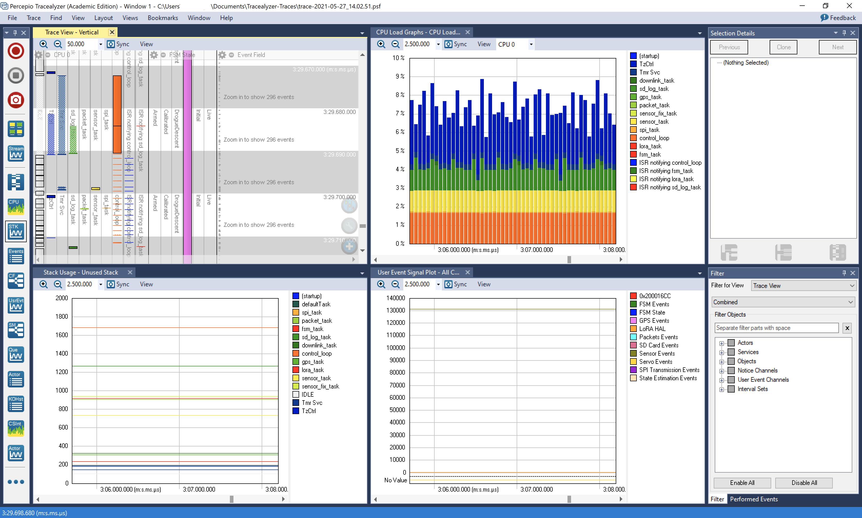
How the team leveraged the visual trace diagnostics functionality of Tracealyzer
The main microcontroller of the guided rocket recovery system is an STM32F4 Arm-based microcontroller running FreeRTOS 10.3.1. The team also have two microcontroller-equipped sensor boards inside the canopy, with their own small batteries and WiFi modules.
The main microcontroller runs a variety of tasks: sampling a bunch of sensors over I2C, logging to the SD card memory, communicating via a LoRa shield with the ground station, and also running state estimation, guidance and the controllers, including instructing the brushless DC motor controller on how much line should be pulled.
From last year’s teams, the team had already heard about Tracealyzer and how this debugging tool had helped them to spot and shave considerable time off certain logging tasks. So the team was eager to use the tool to look at how the RTOS design worked out. Of the many things the team learned these two stand out:
Control loop performance
Control of parachute-payload systems depends on having a good model that accurately captures the relevant aerodynamic effects, the dynamics between parachute and payload, and the influence of wind. The control engineers designed an extensive model and state estimation in MATLAB, which was then transferred onto a microcontroller by generating C code from it.
The team aimed at a frequency of 20 Hz for the control loop, but initially, the team was far from that. The state estimation used up all the CPU power the team had, resulting in about 4 – 5 Hz of sampling frequency. This had to be improved!
First, the team (embarrassingly) noticed that FPU (floating-point unit) support wasn’t activated in FreeRTOS’ configuration, which immediately boosted the performance. After that, using Tracealyzer allowed us to do “rapid prototyping” on the generated code to quantify what exact effect different generation options had on the code’s performance. In the end, the team could single down on the tradeoff between RAM usage and performance that proved optimal for the team’s purposes, and could achieve the desired sampling rate.
Delays in the motor controller
Another thing the team noticed was that after putting all the components together in the final assembly, the motors weren’t running as quickly as before. This was definitely strange and unintended. But looking at the Trace View in Tracealyzer immediately revealed what the issue was: The tail end of the control chain was sending the reference position to an external motor controller over UART.
Increased noise from other components made the STM32F4 unable to recognise the response and it was timing out on the UART transmission, delaying the control loop! With this knowledge, the team lowered the timeout such that all deadlines could still be met, and also fixed the noise issues by altering the electrical design.
Swiss Army steps in to test the prototype
This spring, the team has been on a testing campaign, where they drop the system from a helicopter at heights of 800 to 1500 m above ground in cooperation with the Swiss Armed Forces. You can see a fish-eye view of the system flying in the Swiss Alps above.
The team was all very excited to see the system in action, which also has come to life thanks to the help of Percepio’s Tracealyzer, so a special thanks goes out to Percepio for their continued sponsorship of ARIS and giving us such valuable insight into the performance of the RTOS!