


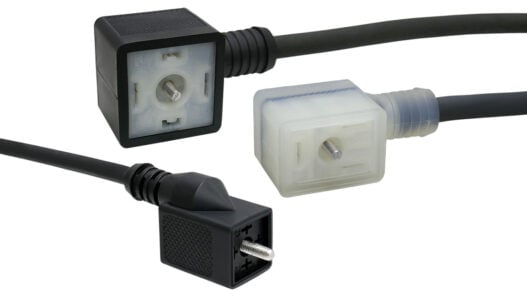


##IMAGE_1_L##Potential applications are electric vehicles and battery management as well as power inverters for solar and wind power stations.
The E524.50 is based on the anisotropic magneto-resistive effect (AMR). The system measures the magnetic field generated by the primary conductor, with the sensitive axis being located at the level of the sensor element. The scale of the AMR effect makes a flux concentrator redundant. The fast amplifiers used in the feedback controlled circuit (closed-loop principle) allow for the wide measurement bandwidth from DC to beyond 500 kHz AC, making the fast detection of the actual quantities of pulse edges possible in particular. Typical total error is 1.5% FS (full scale, max. output signal) over the entire temperature range from -40°C to +125°C, thus below the typical tolerance of about 5% FS shown by current sensors based on the Hall effect.
A special leadframe together with advanced packaging technology enable a “system-in-package” solution (SIP): All system components for sensing the primary current are integrated into a JEDEC compatible SOIC16 package in a standard molding process. Additional mounting (through-hole technology) or soldering processes (e.g. wave soldering) for manufacturing the printed circuit board are unnecessary.
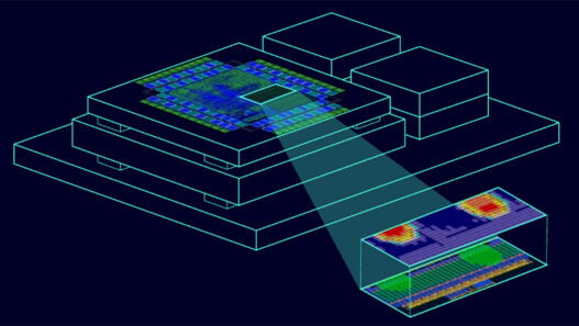
The magnetic field differential is created by leading the primary conductor in a U shape below the sensor package. The sensor is situated on the U’s axis of symmetry. By varying the geometry of the primary conductor, the differential magnetic field desired at the sensor location can be adjusted and optimized for different current ranges and applications. Thus only one current sensor is required, covering a wide range of different primary currents.
https://www.youtube.com/watch?v=elOJfWHUwqg