


This post tells about short-circuited quarter wave transmission line. Quarter wave line resonator is depicted below, it is short-circuited at one end and opened at the other. The length of this transmission line is .
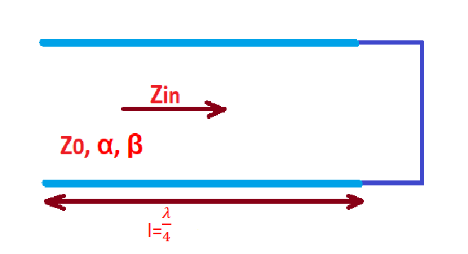
This transmission line as characterised with characteristic impedance , propagation constant , attenuation constant , length , and resonant frequency .
The input impedance of the short-circuited quarter wave transmission line is .
In practice it is usually used low-losses transmission lines where , then . If we have a transmission line with length at resonance . Let’s consider a close to resonance situation . Then .
After simplification . This result can be interpreted like the impedance of parallel RLC circuit . Resistance, capacitance and inductance here can be represented as: .
Unloaded quality factor for this resonator is .
The application of quarter wave transmission line is impedance matching and impedance inversion in size relevant electronic structures, another application in RF/DC coupling in transistor amplifiers.
More educational content can be found at our Reddit community r/ElectronicsEasy.