


This post tells about impedance in microwave network analysis.
Impedance was first used to describe the relationship in AC circuits. Later the concept of impedance was extended as the link between field theory and transmission line theory.
So far we know three types of impedance:
- intrinsic impedance ;
- wave impedance ;
- characteristic impedance .
Let’s consider random one-port network (depicted below).
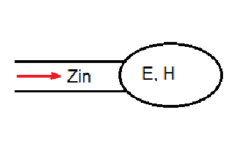
To consider calculate the impedance in the microwave network analysis let’s consider the term of power. The complex power for this network is described with the following expression: . and fields through the network are defined the following way: and .
So we get .
On the other hand, we know for complex power of the network: . Then . As soon as , then .
Real part of the impedance is related to the dissipated power , and imaginary part is related to the energy stored in the network .
Educational content can also be reached via Reddit community r/ElectronicsEasy.