


This post tells about the single-phase half-wave rectifier, it waveforms and characteristics. A single-phase half-wave rectifier circuit is depicted below. This rectifier has a resistive load. This rectifier is the simplest form of diode single-phase rectifiers.
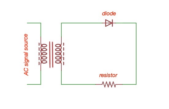
Figure 1. Single-phase half-wave rectifier circuit.
During the positive part the sinus signal diode conducts, during the negative part the sinus signal diode stops conducting. Let’s assume that the voltage transformer is , and the resistor voltage and resistance are and , diode voltage is . Then the wave forms for the diode are the following:

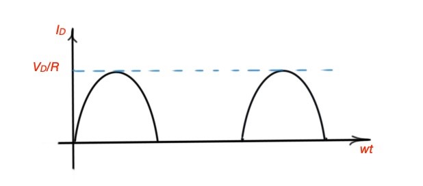
Figure 2. Voltage and current for the diode of the single-phase half-wave rectifier.
The resulting voltage and current of single-phase half-wave rectifier is , .