


For the MOSFET amplifier, input and output voltages of the MOSFET should work in the saturation region of the transference characteristics.
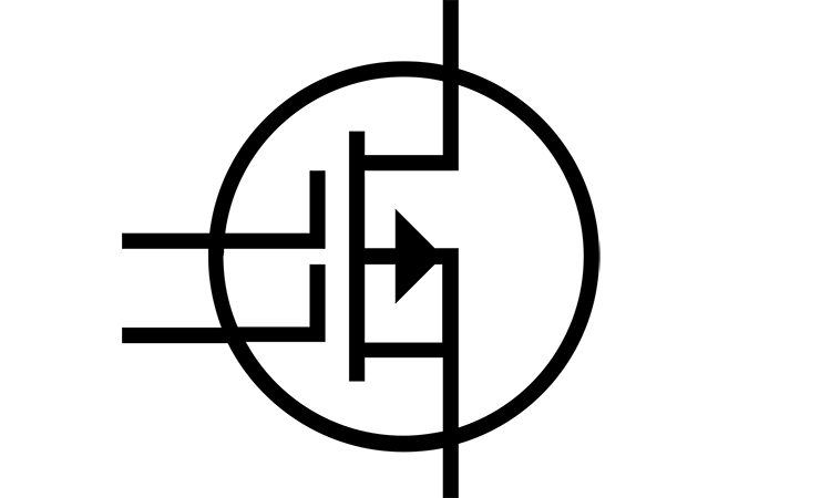
The SR model of the MOSFET amplifier is depicted in Figure 1.
 Figure 1. The MOSFET amplifier circuit.
So, the circuit parameters are =, , , . The amplifier’s gain should be the ratio of the output and input voltage , so the gain . These formulas above offer the possibility to carefully calculate the parameters of the MOSFET amplifier.
The transfer function for the MOSFET amplifier is depicted in Figure 2.
 Figure 2. Transfer characteristics for the MOSFET amplifier circuit.
The large signal analysis and small signal analysis can be applied to the MOSFET amplifier. The large signal analysis deals with the amplifier input signal deviations comparable with the input voltage. This analysis helps us to calculate the relationship between input and output voltages in the operating saturation area of the transfer characteristics.
As we know from the above , . So the ratio of the and is the gain of the amplifier. The volt-ampere characteristics for the MOSFET amplifier is depicted in Figure 3.
 Figure 3. The volt-ampere characteristics for the MOSFET amplifier.
(“Foundations of Analog and digital electronic circuits”, Anant Agarwal and Jeffrey J. Lang, Elsewier.).