Non-linear electric circuits contain non-linear components. Non-linear electric components are characterised with non-linear volt-ampere characteristics, as depicted on the figure below. Non-linear components can be resistive, inductive and capacitive. Non-linear resistor components are fairly large group of components.
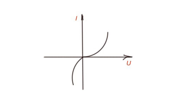
Volt-ampere characteristics for non-linear components
Let’s consider an electric circuit with a non-linear resistor in it. The currents and voltages can be calculated via a graphical method, where we can depict the I-V characteristics of each component in the circuit and calculate the resulting I-V characteristics.
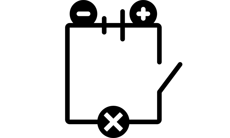
Another method is analytical, that is based on a few equations with key points on the graph. Let’s consider the simplest example. We have a circuit with a linear and non-linear component with the source. The circuit equation (for figure below) is , which is an equation of curve. The key conditions are: , . The tangent of the curve is equal to the resistance of the circuit.
Both methods can be used to calculate the parameters of the circuits with a few non-linear resistances in series or parallel connection.
If we have a few non-linear components in the electric circuit, consisting of a few branches, we can replace them with the equivalent branch.
Let’s consider the circuit depicted on the figure below with three branches containing the voltage sources and non-linear components. Let’s calculate the parameters of the equivalent circuit in this case. To do so we must draw all three volt-ampere characteristics on the same graph. The same volt-ampere characteristics should exist for the equivalent branch. The resulting curve is characterised with the volt-ampere characteristics. As far as there is a voltage source in parallel branches, the volt-ampere characteristics are non-symmetrical.

a
 b
b
Replacement of the circuit with three branches with non-linear components by the one branch circuit.

Volt-ampere characteristics for the replacement of the circuit with three branches with non-linear components by the one branch circuit.
We can also calculate the non-linear circuit with the equivalent generator method. This method is convenient when we have only one non-linear component in our circuit. Here we can represent the circuit as a series connection of non-linear components and voltage source with resistance . Here can be easily calculated from the scheme (below).

Equivalent generator scheme.
We can also characterise the non-linear resistor with its static and differential resistances related to current or voltage. Static resistance of a non-linear resistor characterises the resistor with constant current. is the tangent of the curve angle to the y-axis. Dynamic resistance is the ratio of the small amount of voltage of the non-linear resistor to the small amount of current .
The dynamic resistance can be positive and negative depending on how the current and voltage changes. The dynamic resistance is the most frequently used characteristic of a non-linear resistor. The principle described here can be the basis for current and voltage regulators.
A current regulator is the device that keeps current constant when the voltage through it changes the resistance.
A voltage regulator is the device that keeps voltage constant when the current varies.
The characterisation of regulators can be made with the regulation coefficient – that is the ratio of the voltage increment on the regulator input, to the voltage increment on the regulator output.