


Power integrity continues to grow in significance as FPGAs, ASICs and standard device rails become smaller and tolerances become tighter. The right measurement tools enable fast and accurate characterisation of each rail.
Power rails need to be tested with decreasing voltages and tighter tolerances, yet more precise requirements with measurement errors approaching the required measurement value are problematic. Every mV of measurement error is critical. Sources like high-speed digital signals can also couple onto power rails, requiring GHz of bandwidth to identify.
A low noise oscilloscope
Every oscilloscope contributes internal broadband noise to measurements, therefore a scope with lower noise ensures a better measurement (see Figure 1).
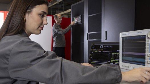
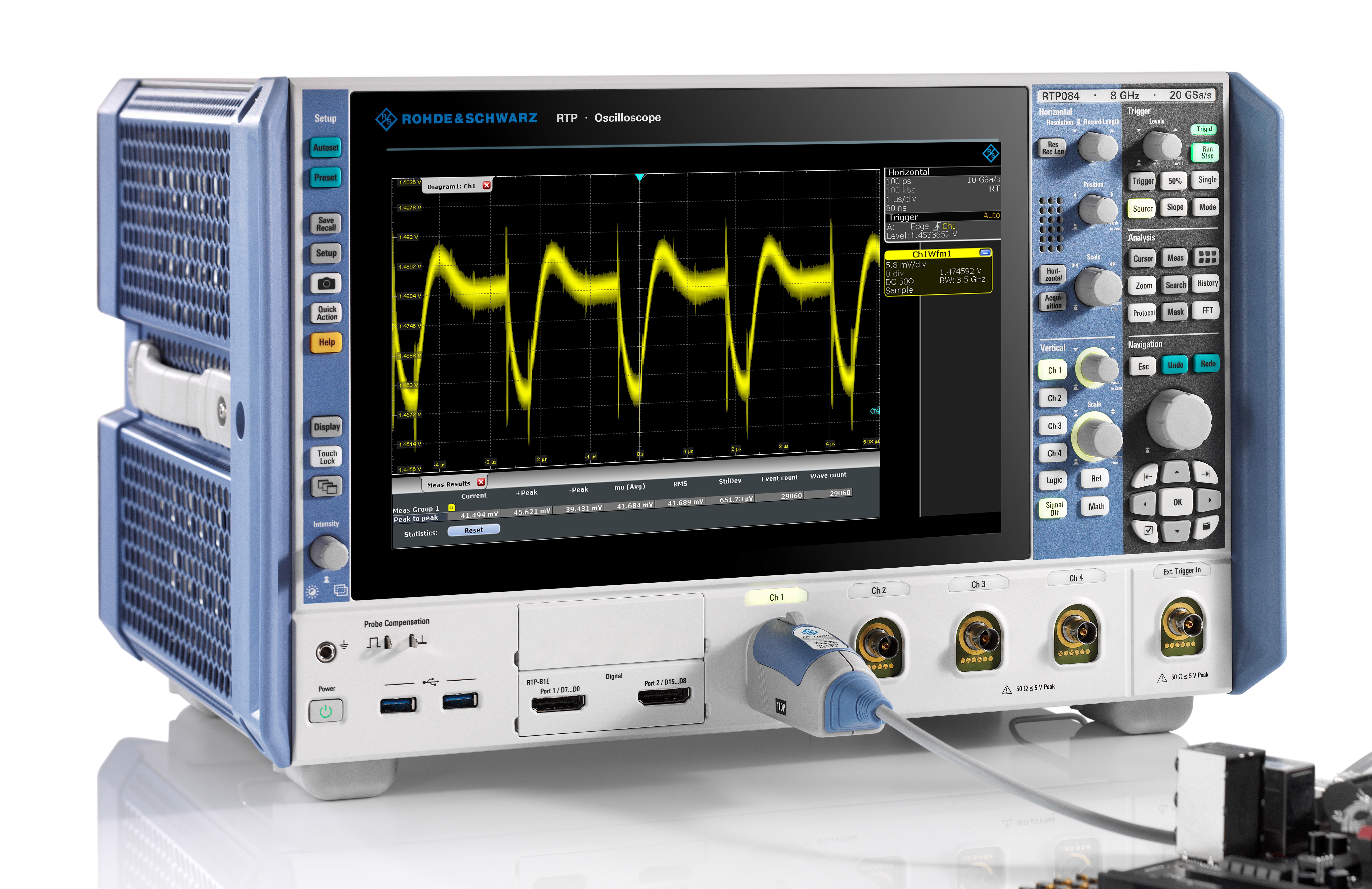 Figure 1: Low-noise, high-bandwidth scopes like the 8GHz RTP from Rohde & Schwarz, characterise DC rails. Probes, such as the 4GHz RT-ZPR40, are designed specifically for power rail measurements
Oscilloscope manufacturers publish alternating current root-mean-squared (AC RMS) noise at each vertical attenuation setting, to help select a low-noise scope. For power integrity, however, the worst case peak-to-peak voltage matters. To check this value, measure the peak-to-peak amplitude at the vertical setting to be used, with no inputs connected.
Many newer scopes offer 10-bit and 12-bit vertical resolution. The additional resolution is almost always obscured by noise unless averaging or high-resolution mode is used. Front end noise has not caught up with advances in vertical resolution for current oscilloscopes, making noise a better indicator of measurement accuracy than resolution.
Many oscilloscopes offer 50Ω and 1MΩ paths. The former generally has lower noise. If using an active probe for power integrity measurements, the probe will use the 50Ω path. Measuring peak-to-peak noise of the oscilloscope with the probe will foreshadow expected measurement error.
Vertical setting
Oscilloscope noise is a function of vertical attenuation settings. Smaller settings have less noise than larger ones. Most oscilloscopes lack sufficient offset to zoom in on power rails. This forces users to choose a lower vertical setting to get the signal on the display, resulting in a less accurate measurement.
There are other ways to compensate for limited internal offset. A blocking capacitor removes DC offset solving the problem of insufficient offset, but eliminates the ability to see low-frequency drift that can occur when subsystems turn on and off. AC coupling on scopes also provides DC blocking. However, AC coupling also eliminates the ability to see low-frequency drift, and for many scopes is limited to the 1MΩ path.
Higher-bandwidth scopes allow viewing of coupled signals such as high-speed clocks riding on the power rail. Since scope and probe noise has linear noise density over broadband frequencies, using maximum bandwidth will result in over-reporting power rail noise values.
In the absence of high-frequency coupled signals, measurement accuracy can be increased by limiting oscilloscope bandwidth to reduce broadband noise.
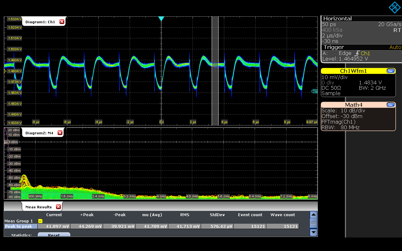 Figure 2: The RTP oscilloscope and RT-ZPR40 power rail probe enables teams to quickly determine both coupled sources and the degree to which they can limit bandwidth while retaining signal content
Experienced users often view the FFT to determine how much bandwidth reduction is possible while still capturing periodic and random disturbances on the power rail (Figure 2). When viewing the FFT, bandwidth can be reduced where no higher-frequency tones are present. Another method is to look at the signal. If the signal shape changes, the bandwidth has been reduced too much (Figure 3). In this example, the 2.5GHz bandwidth setting shows coupled signals that are attenuated and are missed with lower bandwidth limit settings.
Power rail probe
Most oscilloscope manufacturers offer specialised probes for power rail measurements. Large built-in offset compensates for lack of built-in oscilloscope offset, enabling users to choose the lowest vertical attenuation setting for reduced noise. Power rail probes typically have 1:1 attenuation ratios, having significantly less noise than probes with 10:1 attenuation ratio. Power rail probes have high DC impedance, typically 50kΩ, which is significant, since rail impedances are typically in the mΩ range.
Power rail probes can have different connection methods, including a 50Ω pigtail coax as well as a probe browser. Using an SMA pigtail connector requires some forethought, as they work best when designed in. Browsers are more flexible and SMA pigtails are more accurate.
Power rail probes should have sufficient bandwidth to capture coupled signals. Low-noise probe can be achieved with passive probes with 1:1 attenuation ratio, but they have bandwidth limits less than 40MHz. While this approach uses the higher impedance 1MΩ path, probe-inherent, bandwidth-limiting eliminates critical signal content, under-reporting peak-to-peak voltage measurements. Some manufacturers specify guaranteed power rail probe bandwidth, while others provide the typical value.
Ask the vendor whether a probe will work with all oscilloscopes with a probe interface or only with a subset of models. Inserting the probe in unsupported models may damage the scope’s inputs.
Use high DC impedance
Accurate DC values require low measurement loading. Connecting the scope’s 50Ω path directly to a power rail causes the 50Ω loading to change the DC level of the rail. To mitigate this effect, higher measurement impedance is required. The 1MΩ oscilloscope path has a sufficiently high impedance level at DC, but more noise, and is not the path supported with power rail probes. Power rail probes typically have DC impedance of 50kΩ, over a million times more impedance than the rail itself. The DC rail voltage will thus be only very minimally impacted during measurement.
Figure 3: Peak-to-peak voltage measurements using the RTP oscilloscope and RT-ZPR40 power rail probe show the impact of bandwidth-limiting at three different values. The 2.5 GHz bandwidth setting visually shows coupled signals that are attenuated and are missed with lower bandwidth limit settings.
Even the fastest digital oscilloscopes are blind over 90% of the time. Between each acquisition, the scope processes one waveform before acquiring the next. Infrequent events, like worst-case peak-to-peak voltages, can be missed. To compensate, users turn on infinite persistence, automated measurements, waiting until the highest amplitudes are found. Waiting time depends on the target system. Scopes with a fast update rate display the overall noise envelope faster, offering a better graphical view of the DC rail signal behaviour. An oscilloscope updating 1,000 waveforms per second with automated measurements, displays measurement results 20 times faster than an oscilloscope updating 50 waveforms per second with automated measurements enabled. As the number of incorporated power rails increases, each requiring verification, the scope update rate is important.
PCIM Europe Visit Rohde & Schwarz: 6-246