How to improve TPMS design flow
Automobile safety concerns are increasing worldwide and a Tyre Pressure Monitoring System (TPMS) has proven to be a very effective way of reducing single car accidents caused by insufficient tyre pressure. Here, Nicolas Henriet, Senior RF Engineer, Sensata Technologies, describes how the company used high frequency software to enhance the design process and optimise its TPMS performance.
The design team at Sensata was able to perform planar electromagnetic (EM) simulation, Monte-Carlo analysis combined with load-pull techniques, parametric optimisation with component swapping, and EM environmental disturbance analysis - all within a single, integrated design environment, which saved considerable product development time.
TPMS design challenges
Active TPMS technologies must be installed and operate on, or within, the tyre. The latest active TPMS are wireless devices that can monitor several critical tyre conditions and provide timely updates to the car’s computer. Figure 1 (below) shows an overview of a wireless TPMS that communicates with the car’s computer to provide ongoing critical tyre condition data.
In this location on or within the tyre, a TPMS will be subjected to adverse weather conditions, corrosion, physical obstructions, and dirt/grime from road and car conditions. Therefore, TPMS must be extremely rugged, reliable and continue to operate for several years after installation.
As most TPMS must rely on non-replaceable battery power, very low standby current drain and low power sensing/transmission are required to extend the battery life. The extremely wide temperature, pressure, and physical forces in which the TPMS must operate, tend to significantly impact circuit behaviour and performance. In order for TPMS to meet rigorous quality standards, the design must perform within specification over -40°C to +125°C.
PCB analysis
The size and weight constraints of a TPMS require a small Printed Circuit Board (PCB) area, however, cost structures limit the use of custom technologies. In addition, these systems are completely contained, along with onboard power, in a single sealed device embedded with the pressure valve in a tyre. Therefore, careful design of the sensing, control and RF electronics is often implemented using standard Surface Mount Technology (SMT) in highly compact layouts. However, the parasitics introduced by the close-knit PCB traces have an impact on RF behaviour and must be accounted for when determining component values for optimum overall performance.
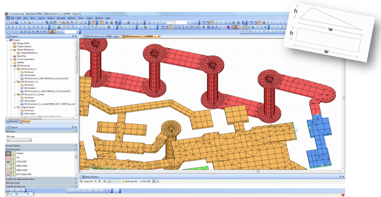
Hence, the PCB trace leads must be carefully modelled and accounted for prior to selecting optimal inductor, capacitor and resistor component values. To overcome these challenges and begin the optimisation process, the designer imported a DXF file of the PCB traces into NI AWR Design Environment, specifically Microwave Office circuit design software.

Above: Figure 2. The PCB’s physical model, such as PCB traces, are imported as a sub circuit to Microwave Office. This sub circuit can be used in circuit simulation as well as in EM simulation
The PCB traces were imported as a sub-circuit component (Figure 2 - above), which was then simulated in a virtual test bench that provided flexibility in probing voltages and currents using AXIEM 3D planar EM solver to extract the PCB behaviour.
Once inside the tool, planar simulation was used to analyse current densities within the EM structure, which can be visualised through colour scaling (Figure 3 - below).

Above: Figure3. The AXIEM 3D planar EM simulator enabled electromagnetic simulation of the imported sub-circuit as an EM structure that can show visual current densities
Additionally, edge ports were created in the EM simulator to reveal voltages between different circuit sections and currents along specified PCB tracks, allowing the insertion of circuit level components, the values of which would later require optimisation.
The designer was able to ensure a proper meshing of the geometry using a built-in ‘snap-to-grid’ function (Figure 4 - below). This solved the predominantly high aspect ratio meshing issues with only negligible modification of the geometries of the PCB traces.

Above: Figure 4. 3D modelling features, such as ‘snap-to-grid’ and others can be used to solve traditionally time consuming and complex meshing issues
Along with the TPMS PCB optimisation, the EM simulator was used to optimise the design of the TPMS antenna. The antenna size, weight and efficiency were an extremely delicate balance in this design. Using shape modifiers and optimisation routines in the simulator, the designer was able to design the optimum structure for the antenna while still meeting impedance, radiation pattern and efficiency goals.
RF circuit simulation
Once a complete PCB trace structure with port assignments was available in the simulator, the external components were modelled and values optimised to meet design specifications. As Sensata desired to leverage a detailed Monte-Carlo analysis, the designer modified each component internally to enable the statistical analysis.
While many applications may not require the level of depth of optimisation that the designer employed in this design, the reliability and robust operating requirements of a TPMS sensor in an automotive environment demands a design that can perform in a wide range of environmental factors and up to ten years on a single battery. Therefore, the multi-level component selection, optimisation, and analysis phases were necessary to meet quality and reliability standards.
Monte-Carlo analysis
In such a critical application, understanding the full spread of the circuit’s operational dynamics helps lead to a robust end design. Most TPMS have non-serviceable batteries and rely on highly efficient designs to prevent the constant need of replacing the component, making power consumption and transmitter efficiency among the utmost concerns in this design. Accurate simulations of Power Added Efficiency (PAE) and current consumption at various output power levels of the optimised impedance matching circuit cut the number of prototypes and tests needed to verify the design.

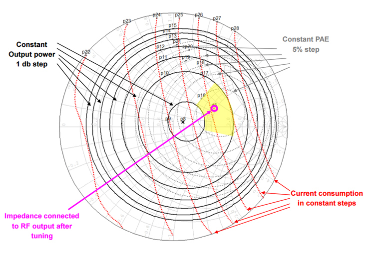
Above: Figure 5. The Monte-Carlo analysis of the load pull measurements of a matching network can reveal the range of performance the network will provide over a wide range of parameters
The designer realised this by performing a Monte-Carlo analysis for spread and stability assessment and improvement using a load-pull measurement technique (Figure 5 - above). The statistical variation of the SMT component values could have led to non-optimal performance if the circuit design wasn’t robust, and the Monte-Carlo analysis might have revealed the need to redesign or identify component combinations that should be avoided in manufacturing. Ultimately, this approach increased the yield and overall reliability of the end product.
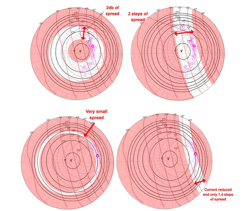
The designer performed this analysis both with and without an optimised network matching as a control experiment to justify the investment in enhancing the design processes with such a sophisticated optimisation process (Figure 6 - below).

Above: Figure 6. Sensata’s custom method approach leveraging Microwave Office optimisation enabled substantial improvements to the current and impedance spreads over the range of analysis parameters
The end results of the optimised impedance matching were a decrease of roughly 1.5dB in the ideal reflection loss and almost two steps of current consumption reduction as compared to the ideal component values.
The Monte-Carlo analysis also revealed a decrease of 0.6 steps of current consumption spread and a decrease of over 1dB of output power spread over the full range of statistical variation. These results indicate that the overall power efficiency over statistical component variations was greatly enhanced, which directly impacts the lifetime of the TPMS.
Environmental disturbances analysis
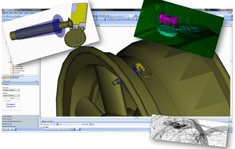
The external environmental parasitics introduced in a final assembly can also greatly impact the TMPS efficiency and performance. Though the impedance match circuitry optimisation revealed substantial internal enhancements, the designer went a step further and developed a car wheel and TPMS model in Analyst 3D finite element method (FEM) EM simulator in order to explore the environmental effects consideration (Figure 7 - opposite). This enabled EM simulation that revealed current patterns antenna radiation patterns, and even component physical body affects on PCB trace performance.
A physical model of the complete TPMS assembly installed within a wheel was used to analyse the current distribution during TPMS transmitter operation. It was evident from the simulation that there was a significant current developed on the inside of the wheel rim that would most likely impact the transmitter performance and radiation pattern of the valve antenna.

Below: Figure 7. As reliability and operational resilience are important in critical automotive applications, Sensata leveraged Analyst 3D FEM EM simulator to gauge the effects of several of the environmental factors in the TPMS real world performance
The analysis revealed that only a small portion of the wheel body and rim impact the TPMS sensor behaviour. So, a smaller parametric shape subsection of the wheel and TPMS assembly were used for more detailed simulations. Otherwise, the computational resources for the rather large wheel assembly would limit the resolution of the simulation.
This is especially important when analysing the effect of SMT component bodies when installed on the PCB tracks. Unpredicted current losses from parasitics could be identified and designed around that could prevent undesirable inefficiencies and internal interference.
Conclusion
The use of high frequency design software was critical in streamlining the design flow and enhancing optimisation of Sensata’s TPMS system. The software also provided a conducive platform for implementing customised scripts that enabled designers to tweak even greater performance from device through optimisation of the circuit components.
As the safety legislation and mandates continue, automobile manufacturers across the globe will need better performing TPMS. High frequency software will become increasingly necessary to overcome the intensive design challenges the automotive industry brings.


