


The system may be required to measure a wide variety of physical phenomenon, so it needs to be flexible and scalable, while also being rugged and reliable, and cost is always a factor. As a result, specifying and building a DAQ system is complex. If the system is over-specified, it will be costly and potentially cumbersome to use. If underspecified, it will be unsuited for current or future tasks. To resolve the dilemma, designers can take a modular approach that starts with a rugged, high-performance chassis with multiple slots for additional processing performance, features, and connectivity options that may be required over time.
This article reviews the performance metrics of DAQ systems that specifiers need to be aware of, including digitisation of analogue signals, Nyquist sampling theorem and aliasing, input ranges, sampling rates, and multiplexed versus simultaneous sampling. It then presents a modular approach based on a National Instruments’ CompactDAQ chassis, analogue and digital I/O modules, and software components including development environment choices, drivers, and analysis/reporting tools.
DAQ requirements and performance metrics
As mentioned, a DAQ at a basic level comprises sensors, signal conditioning, analogue-to-digital converters (ADCs), processors, and associated software (Figure 1). The task for designers is to match the system elements to what’s being measured and analysed while keeping a rein on cost and setup time.
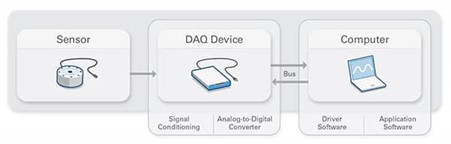
Figure 1: DAQ systems consist of sensors, DAQ measurement devices that provide signal conditioning and data conversion, and computing resources that include drivers and application software. (Image source: NI)
To match the elements, it’s important to understand that precision, signal amplitude, and signal frequency are the fundamental parameters of a DAQ system. These translate into measurement resolution, range, and rate, respectively. In many applications, resolution is the most important consideration. Resolution defines the number of available measurement values. For example, a device with 3-bit resolution can measure 8 possible values (23), while a device with 6-bit resolution can measure 64 (26) possible values (Figure 2). Higher-resolution translates into measurements that more accurately reflect the signal.
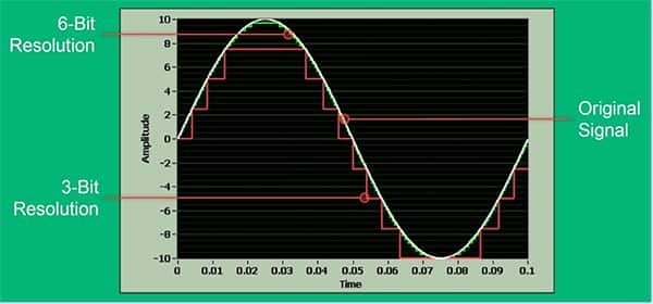
Figure 2: Precision in a DAQ device translates into resolution; a DAQ device with 6-bit resolution provides 8 times the amount of information (8 times as precise) as a device with 3-bit resolution. (Image source: NI)
A given ADC will be set to measure across a set input range such as ±10 volts, and the resolution of the DAQ device applies to the total range. If a measurement is being made over a smaller range, for example ±2 volts, the result is a measurement with a fraction (in this case, about 20%) of the specified resolution of the DAQ device (Figure 3). Using a DAQ device with selectable input ranges can address this issue. Common input ranges include ±10 volts, ±5 volts, ±1 volt and ±0.2 volts. Scaling the input range to suit the signal range results in a higher quality measurement.
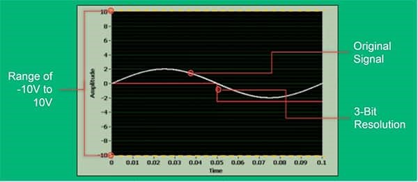
Figure 3: Using a DAQ device with 3-bit resolution and a range of ±10 volts (red lines on left and yellow dotted lines on the top and bottom of the range, respectively) to measure a ±2 volt signal (white sine wave) results in a significant loss of accuracy. (Image source: NI)
Sample rate, Nyquist, and oversampling
Sample rate is the rate at which the ADC converts the analogue input into digital data. Sample rate and resolution can be inversely correlated. Higher sample rates are often possible only by reducing the bits of resolution because a higher rate allows less time for the ADC to digitise the signal. As a result, it’s important to optimise the sample rate.
The Nyquist Sampling Theorem is helpful here: It states that a sample rate, fs, that exceeds twice the maximum signal frequency will result in an accurate measurement of the frequency of the original signal. This is called the Nyquist frequency, fN. To accurately measure the shape and the frequency of the original signal, the Nyquist Theorem requires fs to be 5 to 10 times the maximum signal frequency. Using a sampling rate higher than fN is called oversampling.
In addition to understanding fN, aliasing and ghosting are challenges that need to be dealt with when optimising fs. Aliasing is an effect that causes distortion in the spectrum of a sampled signal due to the sampling rate being too low to capture high-frequency content accurately. Oversampling can eliminate aliasing. Oversampling is also useful to capture fast signal edges, one-time events, and transients. However, if fs is too high, a phenomenon called ghosting can occur during multiplexed sampling.
At high multiplexed sampling rates, the settling time of each input channel becomes a factor. Ghosting happens when the sample rate exceeds the settling time of the DAQ device. At that point, signals on adjacent channels interfere, leading to ghosting and inaccurate measurements (Figure 4).
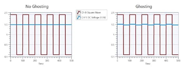
Figure 4: On the left, the sample rate is low enough to allow for proper settling between measurements on channels 0 (red) and 1 (blue). On the right, ghosting occurs because the sample rate is too high, and channel 0 is impacting the measurement on channel 1. (Image source: NI)
The effective sample rate of a DAQ device is impacted by the choice of a simultaneous or multiplexed architecture. Simultaneous sampling uses one ADC per input channel and delivers the full sample rate on all channels, independent of the number of channels (Figure 5).
Simultaneous sampling enables multiple samples to be acquired at once. A simultaneous architecture is relatively expensive and involves more components which can limit the number of channels available in a single DAQ device. In a multiplexed architecture, a multiplexer (mux) is used to share a single ADC among all the channels, reducing the maximum rate available to each channel. Samples are acquired in series with delays between channels. Multiplexed architectures cost less and can result in a DAQ device with a greater channel density.
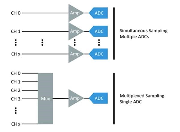
Figure 5: Simultaneous sampling delivers the full data rate on all channels, while in multiplexed sampling, the full sample rate is shared among all channels, resulting in a lower rate per channel. (Image source: NI)
Building a compact DAC system
The first step in building a DAC system is to select the CompactDAQ chassis. Chassis are available with various communications buses including PCI and PCI Express (PCIe), High-Speed USB, PXI and PXI Express (PXIe), and Ethernet 2.0, and from one to 14 slots for NI’s C series I/O modules. For example, the 781156-01 has eight slots and a USB 2.0 interface (Figure 6). Additional measurement types and channels can be added to the system by simply plugging in modules. All modules are automatically detected and synchronised to the clock in the backplane of the chassis.
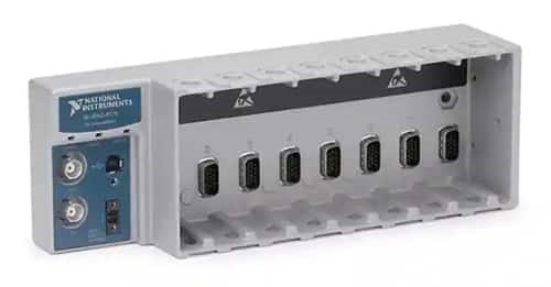
Figure 6: The 781156-01 CompactDAQ chassis has eight slots and a USB 2.0 High-Speed interface. (Image source: NI)
The communications bus is an important part of chassis specification (Table 1). The 60 megabits per second (Mbits/s) delivered by USB is adequate for the majority of applications, and USB has good flexibility and portability. Ethernet can support longer cable distances and distributed DAQ systems in physically large applications. PCI and PCIe buses allow devices to be plugged into a desktop computer for data logging and analysis. PXI and PXIe buses are similar to PCI and PCIe, but offer superior synchronisation capabilities, enabling the consolidation and comparison of large quantities of data.
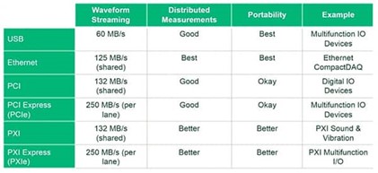
Table 1: DAQ communications bus selection is an important part of chassis selection. The bus should be matched with the needed data transmission rates, distances, and need for portability. (Image source: NI)
Once the chassis has been selected, designers can choose from over 60 C Series modules for measurement, control, and communication applications. C Series modules are available that can connect to virtually any sensor or bus and allow for high-accuracy measurements that meet the demands of DAQ and control applications (Figure 7). These hot swappable modules provide measurement-specific signal conditioning to filter noise and isolate data, analogue-to-digital conversion, plus a variety of input connectors.
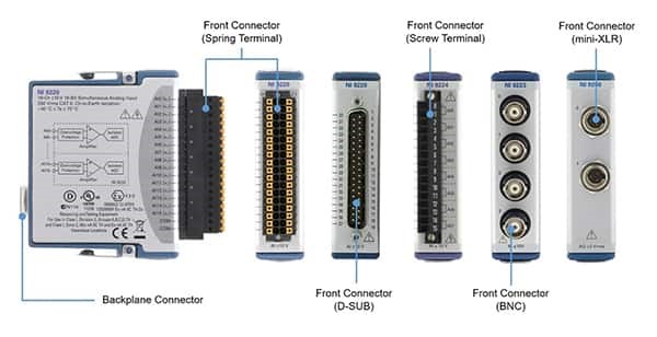
Figure 7: C series modules have a common form factor, can be hot-plugged into any CompactDAQ chassis, and are available with a variety of input connectors to suit the needs of diverse applications. (Image source: NI)
C series modules can be used for many DAQ and control functions including:
- Analogue input modules have up to 16 channels for connectivity with voltage, current, and common sensors for measuring temperature, sound, strain, pressure, load, vibration, and more.
- The NI 9239 is a four-channel general purpose analogue input module. Each channel provides a ±10-volt measurement range with 24-bit resolution and outputs 50 kilosamples per second (kS/s) of data at its maximum sampling rate.
- Analogue output modules are available with 2, 4, and 16 channels and can be used for generating voltage signals and controlling industrial current-driven actuators
- The NI 9263 is a four-channel analogue output module featuring National Institute of Standards and Testing (NIST) traceable calibration, plus overvoltage protection, short-circuit protection, fast slew rate, and high accuracy.
- Digital input and output modules can be used for generating and reading digital signals. Digital input modules are available with 4, 6, 8, 16 and 32 channels, output and bidirectional modules are offered with 8, 16 and 32 channels.
- The NI 9423 is an eight-channel digital input module compatible with 24-volt signals and is designed to work with industrial logic levels and signals for direct connection to an array of industrial switches, transducers, sensors, and other devices.
- The NI 9472 is an eight-channel digital output module compatible with 6 to 30-volt signals and can connect directly to a variety of industrial devices such as actuators, relays, and motors.
Software integration
The final step in building a compact DAQ system is software. The NI-DAQmx application programming interface (API) works directly with a variety of development options including LabVIEW, C, C#, and Python. The API supports seamless operation across all NI DAQ devices and minimizes redevelopment efforts resulting from hardware upgrades or changes, and includes access to documentation, help files, and numerous ready-to-run software examples to jump-start application development.
Developers can dial in the level of programming needed for each project (Figure 8). FlexLogger data logging software provides an intuitive sensor-focused configuration development environment that can integrate with NI’s LabVIEW for custom analysis. The use of LabVIEW supports the option of configuring hardware using interactive analysis panels, or a full-featured programming environment. Advanced developers can use most programming languages to interface directly with the DAQmx API for customisation and performance.

Figure 8: A DAQ software selection flow chart shows how developers can dial in the level of programming they’d like to do for each project. (Image source: NI)
Conclusion
Designing a DAQ can be a complex task if starting from scratch. Sensors, signal conditioning, processing, I/O, and software must meet the task at hand while allowing for modifications and upgrades over time. Instead of stitching the elements together, developers can take a modular approach to quickly and efficiently design a compact DAQ system that includes sensors, hardware, and software, all of which can be swapped over time as the application requirements change.
In addition, the approach shown in this article supports various communications buses, including PCI and PCIe, High-Speed USB, PXI and PXIe, and Ethernet 2.0 to meet specific system requirements. It uses hot swappable modules to provide measurement-specific signal conditioning to filter noise and isolate data, and analogue-to-digital conversion, plus a selection of input connector styles. It’s also flexible and can be integrated with various measurement software including LabVIEW, C, C#, and Python.
The original article can be found on Digikey Electronics.
